Page 266
REPAIR INSTRUCTIONS, PART 1
Valve Rocker Arm Shaft
Reassembly (with J-Tech™ Engine
Brake)
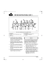
There is a shouldered rocker arm mounting
capscrew at one end of each rocker arm
assembly to ensure proper alignment.
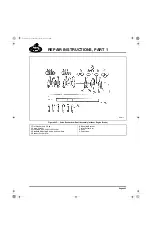
Refer to Figure 296.
The assembly procedure for the rocker arm shaft
of a J-Tech™ brake-equipped engine is nearly
identical to that of the non-brake engine with the
following differences:
앫
An oil supply screw replaces the locating
screw and lock washer.
앫
A spherical jam nut and adjusting screw
replace the standard jam nut and adjusting
screw on the exhaust rocker arms.
The installation procedure is as follows:
1. Lubricate the three adjusting screws and
jam nuts for the
inlet rocker arms
, and
install one in each of the arms.
2. Lubricate the three adjusting screws and
spherical jam nuts for the
exhaust rocker
arms
, and install one in each of the arms.
3. Position the shaft so that the screw locating
hole is in line with the bracket locating screw
hole. The offset side of the bracket must be
positioned toward the right side of the
engine.
4. Assemble the bracket on a press table.
Press the shaft into the bracket until the oil
hole in the shaft is aligned with the hole in
the bracket. Install the oil supply screw to
secure the bracket on the shaft and tighten
the screw to specification, 5 lb-ft (7 N
폷
m).
5. Lubricate the spring washers and install the
washers on the shaft, one on each side of
the mounting bracket.
6. Lubricate the exhaust rocker arm and install
it on the shaft.
7. Install a flat washer and C-clip on the shaft
to retain the exhaust rocker arm.
8. Lubricate the inlet rocker arm and install it
on the shaft.
9. Install a flat washer and C-clip on the shaft
to retain the inlet rocker arm.
10. Install a flat washer and C-clip on the shaft
to position and retain the exhaust rocker arm
at the center position of the shaft.
11. Lubricate the exhaust rocker arm and install
it on the shaft.
12. Lubricate a spring washer, install it on the
shaft next to the exhaust rocker arm and
press the center mounting bracket onto the
shaft. This bracket does not have a threaded
hole on top or an oil hole at the bottom
surface. Align the mounting surface and
offset of the bracket with the bracket already
installed.
13. Lubricate a spring washer and install it on
the shaft next to the center bracket.
14. Lubricate and install the inlet rocker arm on
the shaft.
15. Install a flat washer and C-clip on the shaft
to retain the center inlet rocker arm.
16. Follow steps 10 through 15 to install the
remaining set of rocker arms and mounting
bracket.
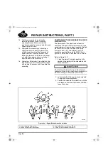
At this point, a used or scrapped cylinder head
can be used as a template for proper bracket
alignment and to ensure mounting surfaces of
each bracket are parallel.
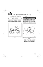
17. Check for proper bracket alignment. Ensure
that mounting surfaces of each bracket are
parallel.
5-111.bk Page 266 Monday, July 10, 2006 2:26 PM
Содержание ASET AC
Страница 6: ...TABLE OF CONTENTS Page iii TABLE OF CONTENTS 5 111 bk Page iii Monday July 10 2006 2 26 PM...
Страница 14: ...INTRODUCTION Page 1 INTRODUCTION 5 111 bk Page 1 Monday July 10 2006 2 26 PM...
Страница 23: ...Page 10 NOTES 5 111 bk Page 10 Monday July 10 2006 2 26 PM...
Страница 24: ...VISUAL IDENTIFICATION Page 11 VISUAL IDENTIFICATION 5 111 bk Page 11 Monday July 10 2006 2 26 PM...
Страница 28: ...DESCRIPTION AND OPERATION Page 15 DESCRIPTION AND OPERATION 5 111 bk Page 15 Monday July 10 2006 2 26 PM...
Страница 96: ...COMPONENT LOCATOR Page 83 COMPONENT LOCATOR 5 111 bk Page 83 Monday July 10 2006 2 26 PM...
Страница 99: ...Page 86 NOTES 5 111 bk Page 86 Monday July 10 2006 2 26 PM...
Страница 100: ...TROUBLESHOOTING Page 87 TROUBLESHOOTING 5 111 bk Page 87 Monday July 10 2006 2 26 PM...
Страница 140: ...MAINTENANCE Page 127 MAINTENANCE 5 111 bk Page 127 Monday July 10 2006 2 26 PM...
Страница 153: ...Page 140 NOTES 5 111 bk Page 140 Monday July 10 2006 2 26 PM...
Страница 154: ...REPAIR INSTRUCTIONS PART 1 Page 141 REPAIR INSTRUCTIONS PART 1 5 111 bk Page 141 Monday July 10 2006 2 26 PM...
Страница 383: ...Page 370 NOTES 5 111 bk Page 370 Monday July 10 2006 2 26 PM...
Страница 384: ...REPAIR INSTRUCTIONS PART 2 Page 371 REPAIR INSTRUCTIONS PART 2 5 111 bk Page 371 Monday July 10 2006 2 26 PM...
Страница 454: ...REPAIR INSTRUCTIONS PART 3 Page 441 REPAIR INSTRUCTIONS PART 3 5 111 bk Page 441 Monday July 10 2006 2 26 PM...
Страница 479: ...Page 466 NOTES 5 111 bk Page 466 Monday July 10 2006 2 26 PM...
Страница 480: ...SPECIFICATIONS Page 467 SPECIFICATIONS 5 111 bk Page 467 Monday July 10 2006 2 26 PM...
Страница 505: ...Page 492 NOTES 5 111 bk Page 492 Monday July 10 2006 2 26 PM...
Страница 506: ...SCHEMATIC ROUTING DIAGRAMS Page 493 SCHEMATIC ROUTING DIAGRAMS 5 111 bk Page 493 Monday July 10 2006 2 26 PM...
Страница 513: ...Page 500 NOTES 5 111 bk Page 500 Monday July 10 2006 2 26 PM...
Страница 514: ...SPECIAL TOOLS EQUIPMENT Page 501 SPECIAL TOOLS EQUIPMENT 5 111 bk Page 501 Monday July 10 2006 2 26 PM...
Страница 519: ...Page 506 NOTES 5 111 bk Page 506 Monday July 10 2006 2 26 PM...
Страница 520: ...APPENDIX Page 507 APPENDIX 5 111 bk Page 507 Monday July 10 2006 2 26 PM...
Страница 528: ...INDEX Page 515 INDEX Index fm Page 515 Monday July 10 2006 2 48 PM...
Страница 535: ...Page 522 NOTES Index fm Page 522 Monday July 10 2006 2 48 PM...


