Page 488
SPECIFICATIONS
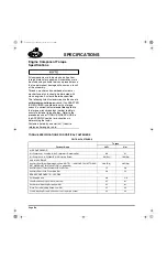
SPECIFICATION FOOTNOTES
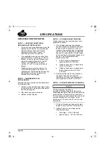
NOTE 1 — AUXILIARY SHAFT GEAR
RETAINING NUT INSTALLATION
앫
A new nut has pre-applied thread locker. No
degreasing of a new nut is recommended.
However, degrease the shaft threads
thoroughly with Loctite
®
Primer-T, or
equivalent, prior to nut installation.
앫
It is acceptable to reuse an auxiliary drive
gear retaining nut. If reusing a nut, the nut
threads, as well as the shaft threads, must
also be thoroughly cleaned with Loctite
®
Primer-T, or equivalent. Then, apply
Loctite
®
271 or 277 on the nut and shaft
threads.
앫
Whether using a new or revised nut, it is
critical that the ground face of the nut (if
applicable) be installed toward the gear. Any
identifications on the nut face must be
installed away from the gear.
NOTE 2 — MAIN BEARING CAP
INSTALLATION
Main bearing cap assembly shall be performed in
the following steps:
1. Buttress screws installed finger-tight in order
to align the hole in the block and the hole in
the main bearing cap.
2. Main bearing capscrews torqued.
3. Buttress screws torqued.
NOTE 3 — CYLINDER HEAD TORQUING
Cylinder head assembly and torquing is to be
performed as follows:
1. Oil all cylinder head capscrew bosses,
capscrew threads and washers with clean
engine oil prior to assembly. Do not oil
threads in the cylinder block. Using torque
wrench J 24407, or equivalent, tighten the
capscrews to specification in three stages
on any one head in the proper sequence, as
shown in the “Engine Reassembly”
procedures section.
a.
Initially, torque all capscrews in
sequence to 50 lb-ft (68 N
폷
m).
b.
Tighten all capscrews in sequence to
125 lb-ft (170 N
폷
m).
c.
Tighten all capscrews in sequence to
the final torque value of 205 lb-ft
(278 N
폷
m).
2. After completing the run-in procedure, in
sequence, back off each capscrew
individually until free. Then, retorque the
same capscrew to 205 lb-ft (278 N
폷
m).
NOTE 4 — EXHAUST MANIFOLD TORQUING
On some engines, the exhaust
manifold-to-cylinder head stud hole may be
drilled deep enough to allow the stud to enter the
push rod bore. In these instances, the 20 lb-ft
(27 N
폷
m) torque may not be reached until the stud
contacts the push rod. In all cases, a stud
protrusion of 1.75 inches (44.45 mm) must be
maintained.
1. Oil the nut threads and flanges with clean
engine oil and install the 12 retaining nuts.
2. Tighten the nuts in two stages per the
following sequence:
앫
First stage — 50 lb-ft (68 N
폷
m)
앫
Second stage — 100 lb-ft (136 N
폷
m)
5-111.bk Page 488 Monday, July 10, 2006 2:26 PM
Содержание ASET AC
Страница 6: ...TABLE OF CONTENTS Page iii TABLE OF CONTENTS 5 111 bk Page iii Monday July 10 2006 2 26 PM...
Страница 14: ...INTRODUCTION Page 1 INTRODUCTION 5 111 bk Page 1 Monday July 10 2006 2 26 PM...
Страница 23: ...Page 10 NOTES 5 111 bk Page 10 Monday July 10 2006 2 26 PM...
Страница 24: ...VISUAL IDENTIFICATION Page 11 VISUAL IDENTIFICATION 5 111 bk Page 11 Monday July 10 2006 2 26 PM...
Страница 28: ...DESCRIPTION AND OPERATION Page 15 DESCRIPTION AND OPERATION 5 111 bk Page 15 Monday July 10 2006 2 26 PM...
Страница 96: ...COMPONENT LOCATOR Page 83 COMPONENT LOCATOR 5 111 bk Page 83 Monday July 10 2006 2 26 PM...
Страница 99: ...Page 86 NOTES 5 111 bk Page 86 Monday July 10 2006 2 26 PM...
Страница 100: ...TROUBLESHOOTING Page 87 TROUBLESHOOTING 5 111 bk Page 87 Monday July 10 2006 2 26 PM...
Страница 140: ...MAINTENANCE Page 127 MAINTENANCE 5 111 bk Page 127 Monday July 10 2006 2 26 PM...
Страница 153: ...Page 140 NOTES 5 111 bk Page 140 Monday July 10 2006 2 26 PM...
Страница 154: ...REPAIR INSTRUCTIONS PART 1 Page 141 REPAIR INSTRUCTIONS PART 1 5 111 bk Page 141 Monday July 10 2006 2 26 PM...
Страница 383: ...Page 370 NOTES 5 111 bk Page 370 Monday July 10 2006 2 26 PM...
Страница 384: ...REPAIR INSTRUCTIONS PART 2 Page 371 REPAIR INSTRUCTIONS PART 2 5 111 bk Page 371 Monday July 10 2006 2 26 PM...
Страница 454: ...REPAIR INSTRUCTIONS PART 3 Page 441 REPAIR INSTRUCTIONS PART 3 5 111 bk Page 441 Monday July 10 2006 2 26 PM...
Страница 479: ...Page 466 NOTES 5 111 bk Page 466 Monday July 10 2006 2 26 PM...
Страница 480: ...SPECIFICATIONS Page 467 SPECIFICATIONS 5 111 bk Page 467 Monday July 10 2006 2 26 PM...
Страница 505: ...Page 492 NOTES 5 111 bk Page 492 Monday July 10 2006 2 26 PM...
Страница 506: ...SCHEMATIC ROUTING DIAGRAMS Page 493 SCHEMATIC ROUTING DIAGRAMS 5 111 bk Page 493 Monday July 10 2006 2 26 PM...
Страница 513: ...Page 500 NOTES 5 111 bk Page 500 Monday July 10 2006 2 26 PM...
Страница 514: ...SPECIAL TOOLS EQUIPMENT Page 501 SPECIAL TOOLS EQUIPMENT 5 111 bk Page 501 Monday July 10 2006 2 26 PM...
Страница 519: ...Page 506 NOTES 5 111 bk Page 506 Monday July 10 2006 2 26 PM...
Страница 520: ...APPENDIX Page 507 APPENDIX 5 111 bk Page 507 Monday July 10 2006 2 26 PM...
Страница 528: ...INDEX Page 515 INDEX Index fm Page 515 Monday July 10 2006 2 48 PM...
Страница 535: ...Page 522 NOTES Index fm Page 522 Monday July 10 2006 2 48 PM...


