REPAIR INSTRUCTIONS, PART 2
Page 435
VTG Actuating System Calibration
The VTG actuating system must be recalibrated
for proper open and closed vane position
voltages and full stop-to-stop travel whenever
parts are replaced, or when diagnosing certain
conditions (such as an active 4-5 fault code).
Recalibrate the VTG actuating system during any
of the following circumstances:
앫
Turbocharger replacement
앫
VTG actuator replacement
앫
Actuator control valve replacement
앫
Active code 4-5, MID 128, PID269, FMI7
(Refer to the V-MAC
®
III Service Manual,
8-311.)
앫
Complaints of low power or low boost
pressure
VTG CALIBRATION TEST
To perform the VTG calibration test, use
V-MAC
®
III Support Software,
Service
Diagnostics.
The VTG calibration test is located
within
Special Diagnostic Modes, VTG Vane
Position Calibration
.
When performing the VTG Vane Position
Calibration test, engine coolant temperature must
be above 140
°
F (60
°
C), engine not running, and
the key switch in the ON position. Air system
pressure (both primary and secondary) must be
at least 110 psi. Air system pressure at 110 psi is
mandatory to ensure that at all times during the
calibration procedures, the vane actuator
receives a minimum of 95 psi. This pressure is
required for the vanes to reach full travel.
If the turbocharger is too hot to touch, the engine
should be run at an idle, then allowed to cool
before the calibration procedure is performed.
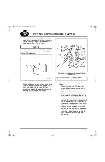
During the calibration test, the actuator rod must
be observed to ensure that full rod travel takes
place, and that the vane operating lever reaches
both the upper and lower stops. If the actuator
does not visibly reach the full stop positions, the
test results have failed, even if the diagnostic tool
reports a successful test. If the actuator did not
reach the full stop positions, either air system
pressure was too low, or there was a mechanical
problem with the vane operating lever, actuator,
control valve, etc., that must be resolved. Verify
that air system pressure is at least 110 psi (95 psi
delivered to the actuator), and check the actuator
and vanes for proper function as outlined under
the heading “Checking Actuator and Vane
Function.”
CALIBRATING ACTUATOR ROD TRAVEL
If the calibration test results indicated that
adjustment of actuator rod travel is necessary,
adjust the rod as follows:
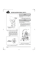
1. Loosen the actuator rod end jam nut while
holding the rod end with an open-end
wrench to prevent the actuator rod from
twisting.
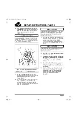
2. Disconnect the air line from the 90-degree
fitting at the top of the actuator.
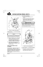
3. Connect a regulated shop air supply (with a
pressure gauge) to the actuator, and apply
40–60 psi. Be careful not to apply pressure
greater than 100 psi, as damage to the
actuator will result.
533
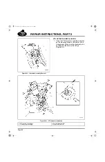
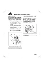
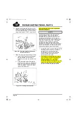
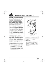
Figure 533 — Regulated Shop Air Connected to Actuator
1. Regulated Shop Air
Supply Line
2. Vane Actuator
5-111.bk Page 435 Monday, July 10, 2006 2:26 PM
Содержание ASET AC
Страница 6: ...TABLE OF CONTENTS Page iii TABLE OF CONTENTS 5 111 bk Page iii Monday July 10 2006 2 26 PM...
Страница 14: ...INTRODUCTION Page 1 INTRODUCTION 5 111 bk Page 1 Monday July 10 2006 2 26 PM...
Страница 23: ...Page 10 NOTES 5 111 bk Page 10 Monday July 10 2006 2 26 PM...
Страница 24: ...VISUAL IDENTIFICATION Page 11 VISUAL IDENTIFICATION 5 111 bk Page 11 Monday July 10 2006 2 26 PM...
Страница 28: ...DESCRIPTION AND OPERATION Page 15 DESCRIPTION AND OPERATION 5 111 bk Page 15 Monday July 10 2006 2 26 PM...
Страница 96: ...COMPONENT LOCATOR Page 83 COMPONENT LOCATOR 5 111 bk Page 83 Monday July 10 2006 2 26 PM...
Страница 99: ...Page 86 NOTES 5 111 bk Page 86 Monday July 10 2006 2 26 PM...
Страница 100: ...TROUBLESHOOTING Page 87 TROUBLESHOOTING 5 111 bk Page 87 Monday July 10 2006 2 26 PM...
Страница 140: ...MAINTENANCE Page 127 MAINTENANCE 5 111 bk Page 127 Monday July 10 2006 2 26 PM...
Страница 153: ...Page 140 NOTES 5 111 bk Page 140 Monday July 10 2006 2 26 PM...
Страница 154: ...REPAIR INSTRUCTIONS PART 1 Page 141 REPAIR INSTRUCTIONS PART 1 5 111 bk Page 141 Monday July 10 2006 2 26 PM...
Страница 383: ...Page 370 NOTES 5 111 bk Page 370 Monday July 10 2006 2 26 PM...
Страница 384: ...REPAIR INSTRUCTIONS PART 2 Page 371 REPAIR INSTRUCTIONS PART 2 5 111 bk Page 371 Monday July 10 2006 2 26 PM...
Страница 454: ...REPAIR INSTRUCTIONS PART 3 Page 441 REPAIR INSTRUCTIONS PART 3 5 111 bk Page 441 Monday July 10 2006 2 26 PM...
Страница 479: ...Page 466 NOTES 5 111 bk Page 466 Monday July 10 2006 2 26 PM...
Страница 480: ...SPECIFICATIONS Page 467 SPECIFICATIONS 5 111 bk Page 467 Monday July 10 2006 2 26 PM...
Страница 505: ...Page 492 NOTES 5 111 bk Page 492 Monday July 10 2006 2 26 PM...
Страница 506: ...SCHEMATIC ROUTING DIAGRAMS Page 493 SCHEMATIC ROUTING DIAGRAMS 5 111 bk Page 493 Monday July 10 2006 2 26 PM...
Страница 513: ...Page 500 NOTES 5 111 bk Page 500 Monday July 10 2006 2 26 PM...
Страница 514: ...SPECIAL TOOLS EQUIPMENT Page 501 SPECIAL TOOLS EQUIPMENT 5 111 bk Page 501 Monday July 10 2006 2 26 PM...
Страница 519: ...Page 506 NOTES 5 111 bk Page 506 Monday July 10 2006 2 26 PM...
Страница 520: ...APPENDIX Page 507 APPENDIX 5 111 bk Page 507 Monday July 10 2006 2 26 PM...
Страница 528: ...INDEX Page 515 INDEX Index fm Page 515 Monday July 10 2006 2 48 PM...
Страница 535: ...Page 522 NOTES Index fm Page 522 Monday July 10 2006 2 48 PM...


