REPAIR INSTRUCTIONS, PART 1
Page 193
CUTTING THE COUNTERBORE
Refer back to Figure 190.
Measure each counterbore depth as the recut is
being performed. The goal is to provide a depth
where only a single shim is necessary to obtain
the proper cylinder sleeve stand-up height.
1. Fill the oil fill tube with 30W nondetergent oil
to maintain lubrication during use.
2. Back off the lower depth-set collar two
increments or less, and tighten the
thumbscrew securely.
3. Cut the counterbore by turning the T-handle
clockwise while maintaining constant
downward pressure on the tool. Stop the
handle in a different position to avoid
creating a ridge in the counterbore.
4. Continue backing off the lower depth-set
collar, no more than two graduations per cut.
Check the depth measurement between
each adjustment. Plan to remove 0.001 inch
(0.025 mm) on the final cut to meet the final
predetermined counterbore depth. This
ensures achieving a very fine machined
finish.
5. Remove the tool from the cylinder bore.
a.
Loosen the two cutter bit hold-down
capscrews and rotate the cutter bit
adjusting screw counterclockwise until
the cutter bit is retracted into the cutter
plate.
b.
Remove the four machine hold-down
bolts and special washers.
c.
Remove the tool from the cylinder bore.
6. Follow steps 1 through 5 for the remaining
cylinders.
COUNTERBORE DEPTH MEASUREMENT
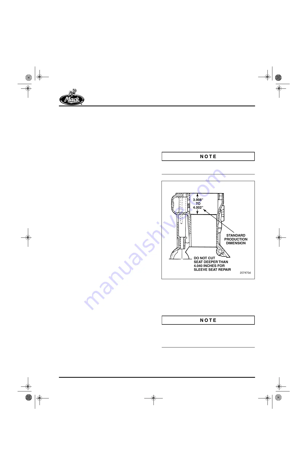
Measure the counterbore depth (Figure 191) and
calculate the shims needed to obtain proper
cylinder sleeve stand-up height. Single shim
repairs should be performed whenever possible.
Shims can be ordered through the MACK Parts
System using part Nos. 505GC26P2, P3 ,P4,
P10, P12, P14, P20, P31 and P42. The shim “P”
number signifies shim thickness, i.e., P14 is
0.014-inch thick. The only exceptions to this are
the P30 which is 0.031
″
and P40 which is actually
0.042
″
. When installing shims, always use the
thickest shims and the least amount of shims as
possible to obtain the proper sleeve stand-up
height. Use a single shim whenever possible, and
if it is necessary to use more than a single shim,
use the fewest shims possible. Also because very
thin shims can be displaced, avoid the use of the
0.002, 0.003 and 0.004 shim sizes whenever
possible.
The current standard production counterbore
depth is 3.998–4.002 inches.
191
Figure 191 — Counterbore Depth Measurement
Effective March 2004, the nominal inside
diameter of all the shims was reduced by 0.064
″
(1.625 mm) (from 5.225
″
[132.715 mm] to 5.161
″
[131.089 mm]). This change allows for a better fit
between the shim and the liner.
If necessary, it is acceptable to use a combination
of shims having the 5.225
″
(132.715 mm) and the
5.161
″
(131.089 mm) inside diameters on the
same sleeve seat.
5-111.bk Page 193 Monday, July 10, 2006 2:26 PM
Содержание ASET AC
Страница 6: ...TABLE OF CONTENTS Page iii TABLE OF CONTENTS 5 111 bk Page iii Monday July 10 2006 2 26 PM...
Страница 14: ...INTRODUCTION Page 1 INTRODUCTION 5 111 bk Page 1 Monday July 10 2006 2 26 PM...
Страница 23: ...Page 10 NOTES 5 111 bk Page 10 Monday July 10 2006 2 26 PM...
Страница 24: ...VISUAL IDENTIFICATION Page 11 VISUAL IDENTIFICATION 5 111 bk Page 11 Monday July 10 2006 2 26 PM...
Страница 28: ...DESCRIPTION AND OPERATION Page 15 DESCRIPTION AND OPERATION 5 111 bk Page 15 Monday July 10 2006 2 26 PM...
Страница 96: ...COMPONENT LOCATOR Page 83 COMPONENT LOCATOR 5 111 bk Page 83 Monday July 10 2006 2 26 PM...
Страница 99: ...Page 86 NOTES 5 111 bk Page 86 Monday July 10 2006 2 26 PM...
Страница 100: ...TROUBLESHOOTING Page 87 TROUBLESHOOTING 5 111 bk Page 87 Monday July 10 2006 2 26 PM...
Страница 140: ...MAINTENANCE Page 127 MAINTENANCE 5 111 bk Page 127 Monday July 10 2006 2 26 PM...
Страница 153: ...Page 140 NOTES 5 111 bk Page 140 Monday July 10 2006 2 26 PM...
Страница 154: ...REPAIR INSTRUCTIONS PART 1 Page 141 REPAIR INSTRUCTIONS PART 1 5 111 bk Page 141 Monday July 10 2006 2 26 PM...
Страница 383: ...Page 370 NOTES 5 111 bk Page 370 Monday July 10 2006 2 26 PM...
Страница 384: ...REPAIR INSTRUCTIONS PART 2 Page 371 REPAIR INSTRUCTIONS PART 2 5 111 bk Page 371 Monday July 10 2006 2 26 PM...
Страница 454: ...REPAIR INSTRUCTIONS PART 3 Page 441 REPAIR INSTRUCTIONS PART 3 5 111 bk Page 441 Monday July 10 2006 2 26 PM...
Страница 479: ...Page 466 NOTES 5 111 bk Page 466 Monday July 10 2006 2 26 PM...
Страница 480: ...SPECIFICATIONS Page 467 SPECIFICATIONS 5 111 bk Page 467 Monday July 10 2006 2 26 PM...
Страница 505: ...Page 492 NOTES 5 111 bk Page 492 Monday July 10 2006 2 26 PM...
Страница 506: ...SCHEMATIC ROUTING DIAGRAMS Page 493 SCHEMATIC ROUTING DIAGRAMS 5 111 bk Page 493 Monday July 10 2006 2 26 PM...
Страница 513: ...Page 500 NOTES 5 111 bk Page 500 Monday July 10 2006 2 26 PM...
Страница 514: ...SPECIAL TOOLS EQUIPMENT Page 501 SPECIAL TOOLS EQUIPMENT 5 111 bk Page 501 Monday July 10 2006 2 26 PM...
Страница 519: ...Page 506 NOTES 5 111 bk Page 506 Monday July 10 2006 2 26 PM...
Страница 520: ...APPENDIX Page 507 APPENDIX 5 111 bk Page 507 Monday July 10 2006 2 26 PM...
Страница 528: ...INDEX Page 515 INDEX Index fm Page 515 Monday July 10 2006 2 48 PM...
Страница 535: ...Page 522 NOTES Index fm Page 522 Monday July 10 2006 2 48 PM...

