REPAIR INSTRUCTIONS, PART 3
Page 461
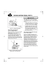
576
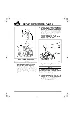
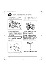
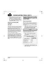
Figure 576 — Engine Speed Sensor
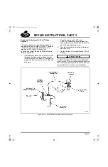
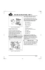
Engine Position Sensor
Installation of the engine position sensor
(Figure 577) is the same as the engine speed
sensor except for the first step. When installing
the engine position sensor, make the shim
calculation measurement from the sensor
mounting surface on the front timing gear cover to
the face of the camshaft gear.
Do not measure into one of the sensing holes in
the gear face or an inaccurate measurement will
result.
577
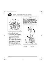
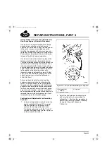
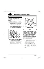
Figure 577 — Engine Position Sensor
Other Engine-Mounted Sensors
The remaining engine-mounted sensors are
thread-mounted and are not adjustable. Mounting
torque values for these sensors are listed under
“Torque Specifications for Engine-Mounted
Sensors” in the SPECIFICATIONS section.
앫
Fuel Temperature
앫
Boost Air Temperature
앫
Boost Air Pressure
앫
Coolant Temperature
앫
Oil Temperature
앫
Oil Pressure
앫
Air Temperature/Humidity
앫
CMCAC Outlet Temperature/Pressure
앫
VTG Position
앫
VTG Wheel-Speed
앫
EGR Temperature
앫
EGR MASS Flow
The
EGR Temperature and MASS Flow
sensors
, however, are an integral part of the
upper EGR gas tube and are not serviceable as
separate items. If replacement is required, the
upper EGR gas tube must be replaced along with
the MASS Flow module to maintain proper
system calibration.
Do not use a non-current E7 English pipe-thread
sensor in place of a metric straight-thread sensor
(or vice versa). Doing so will result in thread
damage to both the sensor and the tapped hole
into which the sensor is installed.
5-111.bk Page 461 Monday, July 10, 2006 2:26 PM
Содержание ASET AC
Страница 6: ...TABLE OF CONTENTS Page iii TABLE OF CONTENTS 5 111 bk Page iii Monday July 10 2006 2 26 PM...
Страница 14: ...INTRODUCTION Page 1 INTRODUCTION 5 111 bk Page 1 Monday July 10 2006 2 26 PM...
Страница 23: ...Page 10 NOTES 5 111 bk Page 10 Monday July 10 2006 2 26 PM...
Страница 24: ...VISUAL IDENTIFICATION Page 11 VISUAL IDENTIFICATION 5 111 bk Page 11 Monday July 10 2006 2 26 PM...
Страница 28: ...DESCRIPTION AND OPERATION Page 15 DESCRIPTION AND OPERATION 5 111 bk Page 15 Monday July 10 2006 2 26 PM...
Страница 96: ...COMPONENT LOCATOR Page 83 COMPONENT LOCATOR 5 111 bk Page 83 Monday July 10 2006 2 26 PM...
Страница 99: ...Page 86 NOTES 5 111 bk Page 86 Monday July 10 2006 2 26 PM...
Страница 100: ...TROUBLESHOOTING Page 87 TROUBLESHOOTING 5 111 bk Page 87 Monday July 10 2006 2 26 PM...
Страница 140: ...MAINTENANCE Page 127 MAINTENANCE 5 111 bk Page 127 Monday July 10 2006 2 26 PM...
Страница 153: ...Page 140 NOTES 5 111 bk Page 140 Monday July 10 2006 2 26 PM...
Страница 154: ...REPAIR INSTRUCTIONS PART 1 Page 141 REPAIR INSTRUCTIONS PART 1 5 111 bk Page 141 Monday July 10 2006 2 26 PM...
Страница 383: ...Page 370 NOTES 5 111 bk Page 370 Monday July 10 2006 2 26 PM...
Страница 384: ...REPAIR INSTRUCTIONS PART 2 Page 371 REPAIR INSTRUCTIONS PART 2 5 111 bk Page 371 Monday July 10 2006 2 26 PM...
Страница 454: ...REPAIR INSTRUCTIONS PART 3 Page 441 REPAIR INSTRUCTIONS PART 3 5 111 bk Page 441 Monday July 10 2006 2 26 PM...
Страница 479: ...Page 466 NOTES 5 111 bk Page 466 Monday July 10 2006 2 26 PM...
Страница 480: ...SPECIFICATIONS Page 467 SPECIFICATIONS 5 111 bk Page 467 Monday July 10 2006 2 26 PM...
Страница 505: ...Page 492 NOTES 5 111 bk Page 492 Monday July 10 2006 2 26 PM...
Страница 506: ...SCHEMATIC ROUTING DIAGRAMS Page 493 SCHEMATIC ROUTING DIAGRAMS 5 111 bk Page 493 Monday July 10 2006 2 26 PM...
Страница 513: ...Page 500 NOTES 5 111 bk Page 500 Monday July 10 2006 2 26 PM...
Страница 514: ...SPECIAL TOOLS EQUIPMENT Page 501 SPECIAL TOOLS EQUIPMENT 5 111 bk Page 501 Monday July 10 2006 2 26 PM...
Страница 519: ...Page 506 NOTES 5 111 bk Page 506 Monday July 10 2006 2 26 PM...
Страница 520: ...APPENDIX Page 507 APPENDIX 5 111 bk Page 507 Monday July 10 2006 2 26 PM...
Страница 528: ...INDEX Page 515 INDEX Index fm Page 515 Monday July 10 2006 2 48 PM...
Страница 535: ...Page 522 NOTES Index fm Page 522 Monday July 10 2006 2 48 PM...

