Page 434
REPAIR INSTRUCTIONS, PART 2
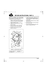
531
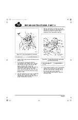
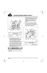
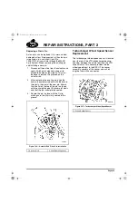
Figure 531 — Vane Position and Wheel Speed Sensor
Harness Routing
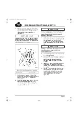
14. Insert the harnesses into the harness clamp,
then assemble the clamp on the
turbocharger compressor V-band clamp
stud. Secure with the existing flat washer
and nut, and tighten the nut to 48 lb-in
(5 N
폷
m). When tightening the harness clamp
nut, take care not to pinch the wires in the
clamp, and make sure the harness clamp
remains in the vertical position. Having the
clamp oriented vertically ensures proper
clearance between the harnesses and the
turbocharger compressor housing, bearing
housing and turbine housing.
Proper routing is essential to avoid heat damage
to the wires and premature failure of the VTG
components.
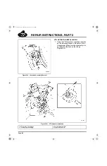
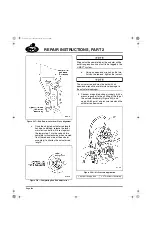
15. Connect the vane position sensor harness
connector to the engine harness connector,
then secure the connector to the isolation
plate mounted on the turbocharger
compressor housing. Use the existing
washers, spacers and bolts previously
removed.
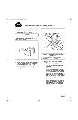
16. Connect the turbocharger wheel speed
sensor connector to the engine harness
connector, then secure the connector on top
of the vane position sensor with two tie
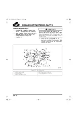
straps as shown in Figure 532.
532
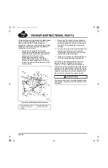
Figure 532 — Turbocharger Wheel Speed Sensor
Connector Mounting
1. Vane Position Sensor
Harness
2. Harness Clamp
2. Wheel Speed Sensor
Harness
1. Tie Straps
2. Wheel Speed Sensor
Harness Connector
5-111.bk Page 434 Monday, July 10, 2006 2:26 PM
Содержание ASET AC
Страница 6: ...TABLE OF CONTENTS Page iii TABLE OF CONTENTS 5 111 bk Page iii Monday July 10 2006 2 26 PM...
Страница 14: ...INTRODUCTION Page 1 INTRODUCTION 5 111 bk Page 1 Monday July 10 2006 2 26 PM...
Страница 23: ...Page 10 NOTES 5 111 bk Page 10 Monday July 10 2006 2 26 PM...
Страница 24: ...VISUAL IDENTIFICATION Page 11 VISUAL IDENTIFICATION 5 111 bk Page 11 Monday July 10 2006 2 26 PM...
Страница 28: ...DESCRIPTION AND OPERATION Page 15 DESCRIPTION AND OPERATION 5 111 bk Page 15 Monday July 10 2006 2 26 PM...
Страница 96: ...COMPONENT LOCATOR Page 83 COMPONENT LOCATOR 5 111 bk Page 83 Monday July 10 2006 2 26 PM...
Страница 99: ...Page 86 NOTES 5 111 bk Page 86 Monday July 10 2006 2 26 PM...
Страница 100: ...TROUBLESHOOTING Page 87 TROUBLESHOOTING 5 111 bk Page 87 Monday July 10 2006 2 26 PM...
Страница 140: ...MAINTENANCE Page 127 MAINTENANCE 5 111 bk Page 127 Monday July 10 2006 2 26 PM...
Страница 153: ...Page 140 NOTES 5 111 bk Page 140 Monday July 10 2006 2 26 PM...
Страница 154: ...REPAIR INSTRUCTIONS PART 1 Page 141 REPAIR INSTRUCTIONS PART 1 5 111 bk Page 141 Monday July 10 2006 2 26 PM...
Страница 383: ...Page 370 NOTES 5 111 bk Page 370 Monday July 10 2006 2 26 PM...
Страница 384: ...REPAIR INSTRUCTIONS PART 2 Page 371 REPAIR INSTRUCTIONS PART 2 5 111 bk Page 371 Monday July 10 2006 2 26 PM...
Страница 454: ...REPAIR INSTRUCTIONS PART 3 Page 441 REPAIR INSTRUCTIONS PART 3 5 111 bk Page 441 Monday July 10 2006 2 26 PM...
Страница 479: ...Page 466 NOTES 5 111 bk Page 466 Monday July 10 2006 2 26 PM...
Страница 480: ...SPECIFICATIONS Page 467 SPECIFICATIONS 5 111 bk Page 467 Monday July 10 2006 2 26 PM...
Страница 505: ...Page 492 NOTES 5 111 bk Page 492 Monday July 10 2006 2 26 PM...
Страница 506: ...SCHEMATIC ROUTING DIAGRAMS Page 493 SCHEMATIC ROUTING DIAGRAMS 5 111 bk Page 493 Monday July 10 2006 2 26 PM...
Страница 513: ...Page 500 NOTES 5 111 bk Page 500 Monday July 10 2006 2 26 PM...
Страница 514: ...SPECIAL TOOLS EQUIPMENT Page 501 SPECIAL TOOLS EQUIPMENT 5 111 bk Page 501 Monday July 10 2006 2 26 PM...
Страница 519: ...Page 506 NOTES 5 111 bk Page 506 Monday July 10 2006 2 26 PM...
Страница 520: ...APPENDIX Page 507 APPENDIX 5 111 bk Page 507 Monday July 10 2006 2 26 PM...
Страница 528: ...INDEX Page 515 INDEX Index fm Page 515 Monday July 10 2006 2 48 PM...
Страница 535: ...Page 522 NOTES Index fm Page 522 Monday July 10 2006 2 48 PM...

