Page 514
APPENDIX
9. Again, pour clean engine oil into the
turbocharger oil inlet port until overflowing,
and then install the oil supply line.
10. Start the engine and let it run at an idle.
Typically, it should take approximately eight
seconds or less for sufficient oil pressure to
build. Allow the engine to idle for
approximately five minutes before
increasing engine speed or driving the
vehicle.
For ASET™ AC engines, disconnect the
connector from the VTG control valve prior to
starting the engine. This will prevent the
turbocharger from reaching excessive speeds
when the engine is first started. Run the engine
for five minutes, and then shut the engine off.
Reconnect the VTG control valve connector and
use the V-MAC
®
service tool to clear the fault
code.
Pre-Lubricating a Turbocharger
After Sitting Idle for an Extended
Period of Time
Turbochargers operate at very high speeds,
temperatures and pressures, making lubrication
of the turbocharger bearings extremely important,
particularly for a turbocharger that has just been
installed, and also for a turbocharger that has not
been operated for a period of time.
When the engine is first started after a new
turbocharger has been installed, or after the
engine has been sitting without being started for
a period of time (approximately 30 days or more),
the bearings are basically dry, and damage to the
bearings due to lack of lubrication can occur
during the first couple minutes of operation.
Except in extreme cases, the turbocharger can
continue to operate for several thousand miles,
but will eventually fail due to the damage caused
at the initial start-up.
Before starting the engine on a vehicle that has
been sitting for an extended period of time
(approximately 30 days), pre-lubricate the
turbocharger as follows:
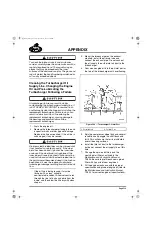
1. Disconnect the oil supply line and the inlet
air duct from the turbocharger.
2. Pour clean engine oil into the oil inlet port
located at the top of the turbocharger until
overflowing.
3. Spin the compressor wheel by hand several
revolutions and wiggle the shaft back and
forth. This will ensure that oil is distributed
over all bearing surfaces.
4. Reconnect the air inlet duct to the
turbocharger.
5. Again, pour clean engine oil into the
turbocharger oil inlet port until overflowing.
6. Reconnect the oil supply line and start the
engine. Allow the engine to idle
approximately five minutes before
increasing engine speed or driving the
vehicle.
For ASET™ AC engines, disconnect the
connector from the VTG control valve prior to
starting the engine. This will prevent the
turbocharger from reaching excessive speeds
when the engine is first started. Run the engine
for five minutes, and then shut the engine off.
Reconnect the VTG control valve connector and
use the V-MAC
®
service tool to clear the fault
code.
5-111.bk Page 514 Monday, July 10, 2006 2:26 PM
Содержание ASET AC
Страница 6: ...TABLE OF CONTENTS Page iii TABLE OF CONTENTS 5 111 bk Page iii Monday July 10 2006 2 26 PM...
Страница 14: ...INTRODUCTION Page 1 INTRODUCTION 5 111 bk Page 1 Monday July 10 2006 2 26 PM...
Страница 23: ...Page 10 NOTES 5 111 bk Page 10 Monday July 10 2006 2 26 PM...
Страница 24: ...VISUAL IDENTIFICATION Page 11 VISUAL IDENTIFICATION 5 111 bk Page 11 Monday July 10 2006 2 26 PM...
Страница 28: ...DESCRIPTION AND OPERATION Page 15 DESCRIPTION AND OPERATION 5 111 bk Page 15 Monday July 10 2006 2 26 PM...
Страница 96: ...COMPONENT LOCATOR Page 83 COMPONENT LOCATOR 5 111 bk Page 83 Monday July 10 2006 2 26 PM...
Страница 99: ...Page 86 NOTES 5 111 bk Page 86 Monday July 10 2006 2 26 PM...
Страница 100: ...TROUBLESHOOTING Page 87 TROUBLESHOOTING 5 111 bk Page 87 Monday July 10 2006 2 26 PM...
Страница 140: ...MAINTENANCE Page 127 MAINTENANCE 5 111 bk Page 127 Monday July 10 2006 2 26 PM...
Страница 153: ...Page 140 NOTES 5 111 bk Page 140 Monday July 10 2006 2 26 PM...
Страница 154: ...REPAIR INSTRUCTIONS PART 1 Page 141 REPAIR INSTRUCTIONS PART 1 5 111 bk Page 141 Monday July 10 2006 2 26 PM...
Страница 383: ...Page 370 NOTES 5 111 bk Page 370 Monday July 10 2006 2 26 PM...
Страница 384: ...REPAIR INSTRUCTIONS PART 2 Page 371 REPAIR INSTRUCTIONS PART 2 5 111 bk Page 371 Monday July 10 2006 2 26 PM...
Страница 454: ...REPAIR INSTRUCTIONS PART 3 Page 441 REPAIR INSTRUCTIONS PART 3 5 111 bk Page 441 Monday July 10 2006 2 26 PM...
Страница 479: ...Page 466 NOTES 5 111 bk Page 466 Monday July 10 2006 2 26 PM...
Страница 480: ...SPECIFICATIONS Page 467 SPECIFICATIONS 5 111 bk Page 467 Monday July 10 2006 2 26 PM...
Страница 505: ...Page 492 NOTES 5 111 bk Page 492 Monday July 10 2006 2 26 PM...
Страница 506: ...SCHEMATIC ROUTING DIAGRAMS Page 493 SCHEMATIC ROUTING DIAGRAMS 5 111 bk Page 493 Monday July 10 2006 2 26 PM...
Страница 513: ...Page 500 NOTES 5 111 bk Page 500 Monday July 10 2006 2 26 PM...
Страница 514: ...SPECIAL TOOLS EQUIPMENT Page 501 SPECIAL TOOLS EQUIPMENT 5 111 bk Page 501 Monday July 10 2006 2 26 PM...
Страница 519: ...Page 506 NOTES 5 111 bk Page 506 Monday July 10 2006 2 26 PM...
Страница 520: ...APPENDIX Page 507 APPENDIX 5 111 bk Page 507 Monday July 10 2006 2 26 PM...
Страница 528: ...INDEX Page 515 INDEX Index fm Page 515 Monday July 10 2006 2 48 PM...
Страница 535: ...Page 522 NOTES Index fm Page 522 Monday July 10 2006 2 48 PM...


