Page 152
REPAIR INSTRUCTIONS, PART 1
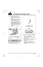
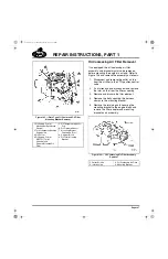
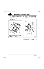
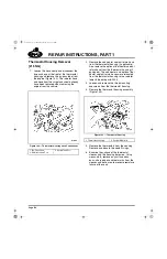
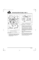
7. Disconnect the fuel lines at the inlet and
outlet ports at the top of the cooling plate
(Figure 133) and position the lines
out-of-way.
Use care when disconnecting the fuel lines to
avoid putting stress on the plate fittings and
damaging the plate. Use two wrenches, one to
support the plate fitting and the second to
disconnect the line.
133
Figure 133 — Cooling Plate Fuel Lines
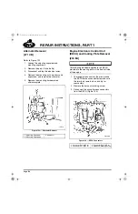
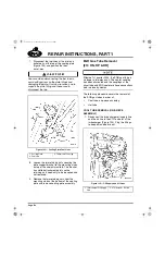
8. Loosen the two retaining nuts securing the
plate support bracket to the mounting studs
on top of the coolant manifold. The bracket
has slotted attachment points so the
retaining nuts need only to be loosened and
not removed.
9. Remove the two retaining nuts from the
mounting studs at the bottom of the cooling
plate and remove cooling plate assembly.
EGR Gas Tube Removal
[214 HN, HP & HR]
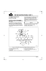
Effective 1st quarter 2004, the EGR cool tube is
no longer a two-piece unit. The center coupling
has been eliminated and the couplings at the
mixer tube and EGR cooler are hose connections
held in place by clamps.
The following procedure covers the removal of
the EGR gas tubes in order of:
앫
Cool tube, one-piece assembly
앫
Hot tube
COOL TUBE REMOVAL (ONE-PIECE
ASSEMBLY)
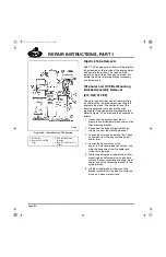
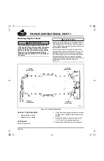
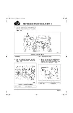
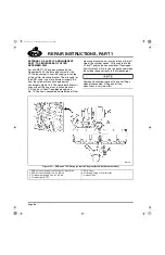
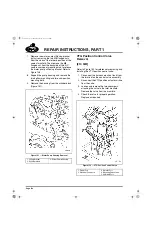
1. Disconnect the turbocharger oil supply line
and the air line to the VTG actuator at the
turbocharger (Figure 134). Plug the fittings
to keep dirt and debris out.
134
Figure 134 — Oil Supply and Air Lines
1. Cooling Plate
2. Fuel Line
3. Thermostat Housing
1. Turbocharger Oil Supply
Line
2. VTG Actuator Air Line
5-111.bk Page 152 Monday, July 10, 2006 2:26 PM
Содержание ASET AC
Страница 6: ...TABLE OF CONTENTS Page iii TABLE OF CONTENTS 5 111 bk Page iii Monday July 10 2006 2 26 PM...
Страница 14: ...INTRODUCTION Page 1 INTRODUCTION 5 111 bk Page 1 Monday July 10 2006 2 26 PM...
Страница 23: ...Page 10 NOTES 5 111 bk Page 10 Monday July 10 2006 2 26 PM...
Страница 24: ...VISUAL IDENTIFICATION Page 11 VISUAL IDENTIFICATION 5 111 bk Page 11 Monday July 10 2006 2 26 PM...
Страница 28: ...DESCRIPTION AND OPERATION Page 15 DESCRIPTION AND OPERATION 5 111 bk Page 15 Monday July 10 2006 2 26 PM...
Страница 96: ...COMPONENT LOCATOR Page 83 COMPONENT LOCATOR 5 111 bk Page 83 Monday July 10 2006 2 26 PM...
Страница 99: ...Page 86 NOTES 5 111 bk Page 86 Monday July 10 2006 2 26 PM...
Страница 100: ...TROUBLESHOOTING Page 87 TROUBLESHOOTING 5 111 bk Page 87 Monday July 10 2006 2 26 PM...
Страница 140: ...MAINTENANCE Page 127 MAINTENANCE 5 111 bk Page 127 Monday July 10 2006 2 26 PM...
Страница 153: ...Page 140 NOTES 5 111 bk Page 140 Monday July 10 2006 2 26 PM...
Страница 154: ...REPAIR INSTRUCTIONS PART 1 Page 141 REPAIR INSTRUCTIONS PART 1 5 111 bk Page 141 Monday July 10 2006 2 26 PM...
Страница 383: ...Page 370 NOTES 5 111 bk Page 370 Monday July 10 2006 2 26 PM...
Страница 384: ...REPAIR INSTRUCTIONS PART 2 Page 371 REPAIR INSTRUCTIONS PART 2 5 111 bk Page 371 Monday July 10 2006 2 26 PM...
Страница 454: ...REPAIR INSTRUCTIONS PART 3 Page 441 REPAIR INSTRUCTIONS PART 3 5 111 bk Page 441 Monday July 10 2006 2 26 PM...
Страница 479: ...Page 466 NOTES 5 111 bk Page 466 Monday July 10 2006 2 26 PM...
Страница 480: ...SPECIFICATIONS Page 467 SPECIFICATIONS 5 111 bk Page 467 Monday July 10 2006 2 26 PM...
Страница 505: ...Page 492 NOTES 5 111 bk Page 492 Monday July 10 2006 2 26 PM...
Страница 506: ...SCHEMATIC ROUTING DIAGRAMS Page 493 SCHEMATIC ROUTING DIAGRAMS 5 111 bk Page 493 Monday July 10 2006 2 26 PM...
Страница 513: ...Page 500 NOTES 5 111 bk Page 500 Monday July 10 2006 2 26 PM...
Страница 514: ...SPECIAL TOOLS EQUIPMENT Page 501 SPECIAL TOOLS EQUIPMENT 5 111 bk Page 501 Monday July 10 2006 2 26 PM...
Страница 519: ...Page 506 NOTES 5 111 bk Page 506 Monday July 10 2006 2 26 PM...
Страница 520: ...APPENDIX Page 507 APPENDIX 5 111 bk Page 507 Monday July 10 2006 2 26 PM...
Страница 528: ...INDEX Page 515 INDEX Index fm Page 515 Monday July 10 2006 2 48 PM...
Страница 535: ...Page 522 NOTES Index fm Page 522 Monday July 10 2006 2 48 PM...

