background image

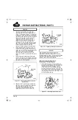
Page 458

REPAIR INSTRUCTIONS, PART 3

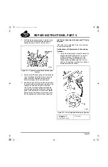
The torque screwdriver may allow the 
adjusting screw to loosen slightly when it 
“clicks” at the pre-set torque. It is important 
to develop a “feel” for when the screwdriver 
click occurs and feel for the actual setting of 
the lash. To develop a feel for when the 
screwdriver will click, slowly turn the 
screwdriver through the function once or 
twice, and for the third time, bring the 
screwdriver just to the point before it clicks. 
Also, at no time should the screwdriver be 
turned clockwise after the click has 
occurred. Always recheck the adjustment.

When tightening the adjusting screw, it is 
important to make sure that the adjusting 
screw jam nut is NOT bottomed against the 
rocker arm, and that the swivel-head 
adjusting screw at the nose end of the 
rocker arm is NOT in contact with the valve 
yoke.

If either the push rod spring or the brake 
actuator plunger are not compressed, brake 
lash is not set correctly and the adjustment 
procedure must be repeated.

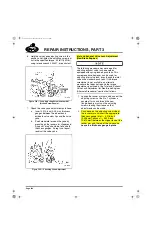
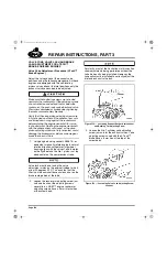
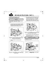
571

Figure 571 — Adjusting Engine Brake Hydraulic 

Actuator Lash

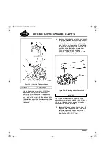
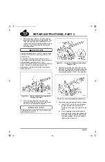
5. Remove the T-handle torque screwdriver, 

then use a hex-bit screwdriver to hold the 
adjusting screw in position. Use an 
accurately calibrated torque wrench to 
tighten the jam nut to 45 lb-ft (61 N

m).

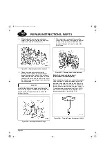
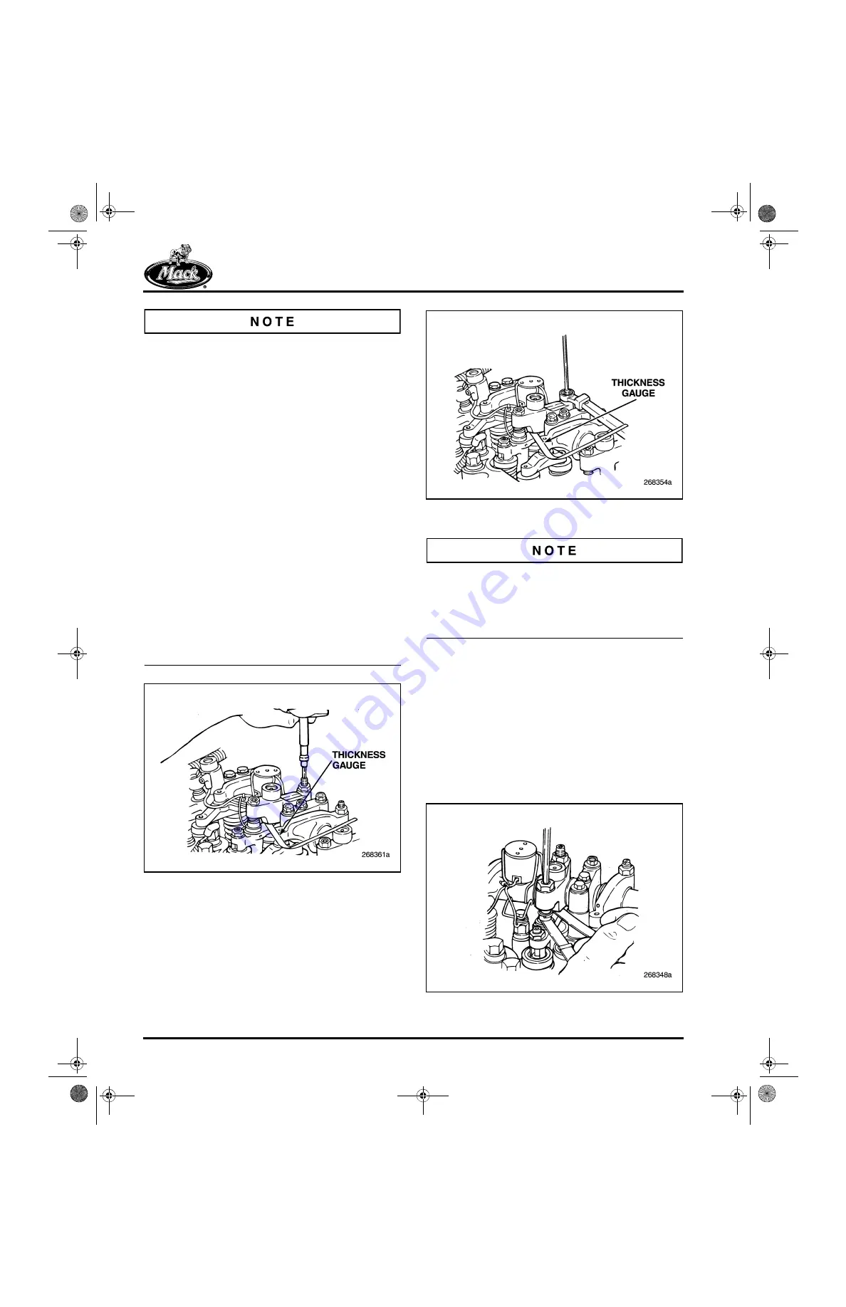
572

Figure 572 — Tightening Adjusting Screw Jam Nut

After completing the brake plunger lash 
adjustment, leave the 0.045-inch (1.14 mm) 
thickness gauge in place. This keeps the plunger 
and push rod spring compressed so that the 
exhaust valve lash can be adjusted.

Exhaust Valve Lash Adjustment 
(PowerLeash™ Brake Engine)

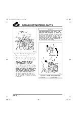
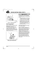
1. With the 0.045-inch (1.14 mm) thickness 

gauge in place between the valve yoke and 
the hydraulic actuator plunger, insert a 
0.024-inch (0.610 mm) thickness gauge 
between the adjusting screw “foot” and the 
valve yoke. Using a 5 mm Allen wrench, turn 
the adjusting screw until a light “drag” is felt 
on the thickness gauge.

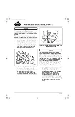
573

Figure 573 — Adjusting Exhaust Valve Lash

5-111.bk  Page 458  Monday, July 10, 2006  2:26 PM

Содержание ASET AC

Страница 1: ...OCTOBER 2006 REVISED 5 111 ASET AC DIESEL ENGINE SERVICE MANUAL for Engines with Exhaust Gas Recirculation EGR...

Страница 2: ...please describe _____________________________________________ _______________________________________________________________ _______________________________________________________________ Did you f...

Страница 3: ...IN THE UNITED STATES BUSINESS REPLY MAIL FIRST CLASS MAIL PERMIT NO 1602 ALLENTOWN PA POSTAGE WILL BE PAID BY ADDRESSEE SERVICE PUBLICATIONS RTS 6S3 MACK TRUCKS INC WORLD HEADQUARTERS PO BOX M ALLENT...

Страница 4: ...ASET AC ENGINE SERVICE MANUAL OCTOBER 2006 REVISED SUPERSEDES ISSUE DATED JANUARY 2005 MACK TRUCKS INC 2006 ENGINE 5 111 1 View of ASET AC Engine 5 111 bk Page i Monday July 10 2006 2 26 PM...

Страница 5: ...chassis The information specifications and illustrations in this publication are based on information that was current at the time of publication No part of this publication may be reproduced stored i...

Страница 6: ...TABLE OF CONTENTS Page iii TABLE OF CONTENTS 5 111 bk Page iii Monday July 10 2006 2 26 PM...

Страница 7: ...43 Camshaft 53 Valve Train 53 Low Pressure Fuel System 60 High Pressure Fuel System 63 High Pressure Fuel Injection Lines 64 Fuel Injector Assemblies 64 Cylinder Block 65 Crankshaft 67 Block Heater 6...

Страница 8: ...Hydraulic Mechanical 121 J Tech Troubleshooting Guide 124 MAINTENANCE 127 LUBRICATION SYSTEM MAINTENANCE FOR ASET ENGINES 128 Crankcase Breather Element Cleaning 128 Oil Level Check 129 Oil and Filter...

Страница 9: ...er Removal 178 Auxiliary Shaft Removal 178 Camshaft Removal 179 Piston and Connecting Rod Assembly Removal 180 Flywheel Removal 182 Flywheel Housing Removal 183 Main Bearing Cap Removal 183 Crankshaft...

Страница 10: ...er Arm Shaft Disassembly with without Engine Brake 262 Inspection 263 Valve Rocker Arm Shaft Reassembly without Engine Brake 264 Valve Rocker Arm Shaft Reassembly with J Tech Engine Brake 266 Valve Ro...

Страница 11: ...ant Manifold Installation 343 Air Inlet Manifold Installation 344 VTG Position Control Valve Installation 344 Water Pump Housing Installation 345 EGR Valve Installation 348 Oil Supply Lines Installati...

Страница 12: ...on 401 EGR SYSTEM SERVICE PROCEDURES IN CHASSIS FOR ASET AC ENGINE 402 Preliminary Steps 402 EGR Gas Tube s Removal and Installation 402 EGR Cooler Removal and Installation 408 EGR Valve Removal and I...

Страница 13: ...Cooling System Flow Diagrams 494 Lubrication System Flow Diagrams 495 Fuel System Flow Diagrams 496 Accessory Drive Belt Routings 499 SPECIAL TOOLS EQUIPMENT 501 ASET ENGINE SPECIAL TOOLS 502 Special...

Страница 14: ...INTRODUCTION Page 1 INTRODUCTION 5 111 bk Page 1 Monday July 10 2006 2 26 PM...

Страница 15: ...ghout the manual Danger indicates an unsafe practice that could result in death or serious personal injury Serious personal injury is considered to be permanent injury from which full recovery is NOT...

Страница 16: ...transmission in neutral set the parking brakes and block the wheels Failure to follow these instructions could produce unexpected vehicle movement which can result in serious personal injury or death...

Страница 17: ...ALWAYS wear safety glasses and protective shoes Avoid injury by being aware of sharp corners and jagged edges Use hoists or jacks to lift or move heavy objects NEVER run engine indoors unless exhaust...

Страница 18: ...TRANSMISSION TRANSFER CASE AND PTO GROUP 400 STEERING AXLES WHEELS AND TIRES DRIVELINE GROUP 500 BRAKES AUXILIARY SYSTEMS GROUP 600 CAB TRUCK BODY GROUP 700 ELECTRICAL The second two digits of the thr...

Страница 19: ...t sq ft to Square Meters sq m 0 0929 Square Yards sq yd to Square Meters sq m 0 8361 Square Miles sq miles to Square Kilometers sq km 2 590 Square Millimeters sq mm to Square Inches sq in 0 00155 Squa...

Страница 20: ...07 Newtons N to Kilograms Force kgf 0 10196 Newtons N to Ounces Force ozf 3 597 Newtons N to Pounds Force lbf 0 2248 Torque Calculations Pound Inches lb in to Newton Meters N m 0 11298 Pound Feet lb f...

Страница 21: ...9612 Kilopascals kPa to Inches of Water in H2O 4 01445 Kilopascals kPa to Pounds per Square Inch psi 0 145 Power Calculations Horsepower hp to Kilowatts kW 0 74627 Kilowatts kW to Horsepower hp 1 34 F...

Страница 22: ...assembly setup and adjustment procedures etc are included in the MAINTENANCE and REPAIR INSTRUCTIONS sections Development of the ASET AC engine has been driven by three basic requirements It is design...

Страница 23: ...Page 10 NOTES 5 111 bk Page 10 Monday July 10 2006 2 26 PM...

Страница 24: ...VISUAL IDENTIFICATION Page 11 VISUAL IDENTIFICATION 5 111 bk Page 11 Monday July 10 2006 2 26 PM...

Страница 25: ...be operated in Australia Item 4 Model Year The four digit number stamped in block 4 represents the year in which the engine was certified Item 5 Federal Family The 12 digit number stamped in block 5 d...

Страница 26: ...ft Figure 1 illustrates the location of the information plate and Figure 2 illustrates its content Figure 3 illustrates a completed sample information plate to be used as an example 1 Figure 1 Engine...

Страница 27: ...ormation plate on the front cylinder head cover the engine is also identified by the engine serial number stamped into the cylinder block This serial number is located on the block right side just bel...

Страница 28: ...DESCRIPTION AND OPERATION Page 15 DESCRIPTION AND OPERATION 5 111 bk Page 15 Monday July 10 2006 2 26 PM...

Страница 29: ...Regardless of the method used CEGR or IEGR both designs are improvements based on changes in several design features of the E7 E Tech current controlled rate shaping CCRS engine The changes are more...

Страница 30: ...the inlet and exhaust valve seat inserts are of a new design that has a smooth rounded radius Figure 7 to achieve the optimum flow of air and exhaust gases in and out of the cylinders With these chan...

Страница 31: ...quired for the CEGR engine exhaust gas recirculation includes components to meter exhaust gases from the exhaust manifold for mixing with the charge air prior to entering the inlet manifold An engine...

Страница 32: ...ne Enhanced engine electronic control unit EECU with increased capacity to measure and manage additional sensor inputs COOLED EXHAUST GAS RECIRCULATION The ASET AC engine with cooled exhaust gas recir...

Страница 33: ...er Tube Coolant Inlet 2 EGR Cooler to Bypass Tube EGR Cooler Coolant Outlet 3 EGR Gas Tube Cool Side 4 EGR Cooler 5 EGR Valve to Cooler Hot Side Tube EGR Gas Inlet 6 EGR Valve 7 EGR Cooler to Mixer Co...

Страница 34: ...Figure 15 is redesigned with mounting surfaces for the EGR valve and turbocharger The valve which is mounted on top the center section of the manifold is a non serviceable unit If a failure should oc...

Страница 35: ...on the hot side of the system On the cool side of the system a 1 5 inch 38 mm diameter one piece tube arrangement is used for routing the exhaust gases from the cooler to the mixer tube on the inlet m...

Страница 36: ...Assembly 1 EGR Cool Tube 2 Upper Clamp 3 Coupling Hose and Clamps 4 Coupling Adapter 5 Mixer Tube 6 EGR MASS Flow Module mounts on back of EECU cooling plate 7 MASS Flow Sensors 8 Lower Clamp 9 Coupli...

Страница 37: ...Clamps used to connect the cool side tubes generally can be reused However for the hot side tube connections the clamps can be reused but the T bolt and nut should not be reused Threads of the clamp...

Страница 38: ...ted to the tube and sensor assembly The entire cool tube with the EGR MASS Flow sensors must be replaced as an assembly along with replacement of the EGR MASS Flow control module should any part tube...

Страница 39: ...s harness connection oil supply and return lines from heat damage an additional shield has been added at the right side of the engine The additional shield surrounds the front section of the exhaust m...

Страница 40: ...ral replacement parts available for the VTG turbocharger Available service parts are as follows VTG Actuator and Position Sensor Assembly Turbo Wheel Speed Sensor VTG Actuator Flange to Turbine Housin...

Страница 41: ...Valve On early production engines prior to May 4 2004 supply air enters the control valve directly from the chassis air system As a result small amounts of oil mist in the chassis air system can cond...

Страница 42: ...he cartridge offset to the left side the fan drive assembly and belt tensioners can be mounted directly at the center in one of several different vertical locations best suited for a vehicle configura...

Страница 43: ...ast into the wall between the two sections The two 1 2 inch diameter holes restrict coolant flow so that a pressure differential is created between the two sections This design allowed the cab heater...

Страница 44: ...eater coolant return hose connection point This change relocates the heater coolant return hoses from the thermostat housing bypass area to a new location on the radiator lower tube 23 Figure 23 Radia...

Страница 45: ...ed to the cylinder heads with three bolts at each coolant port 24 Figure 24 Coolant and Inlet Manifolds Oil Cooler Filter Screen A filter screen in the Y shaped hose at the oil cooler inlet has been a...

Страница 46: ...under the higher exhaust manifold back pressures The dual spring configuration also requires a change in the design of the valve rotator the exhaust valve guide and the valve stem seal Current produc...

Страница 47: ...ear 2003 28 Figure 28 Dual Exhaust Springs Mid Year 2003 and Later 1 Spring Rotator Tip End 2 Hardened Spring Washer 3 Exhaust Spring Outer 4 Exhaust Spring Inner 1 Exhaust Spring Outer 2 Exhaust Spri...

Страница 48: ...with spring loaded push rods at the exhaust locations the same as those phased into production on the E Tech engine These push rod assemblies have a spring at the rocker arm end and are designed to k...

Страница 49: ...fully compressed the push rod becomes solid when the internal stops of the upper and lower spring seats contact each other During the valve closing cycle as the lifter roller travels down the ramp and...

Страница 50: ...32 Oil Dipstick Tube Left Side Installation AC Engine An improved centrifugal oil filter assembly was introduced in ASET AC engines in August 2003 This new centrifugal filter is called Centri Max ULT...

Страница 51: ...ing Variable geometry turbocharger Exhaust gas recirculation Inputs for the three EECU control loops come from 16 sensors six of which are new for the AC CEGR engine These include chassis mounted as w...

Страница 52: ...s Right Side 1 VTG Wheel Speed Sensor in Bearing Housing 2 VTG Position Sensor 3 Connector to Fan Speed Sensor 4 To Chassis Mounted Compressor Discharge Temperature Sensor 5 Engine Position Sensor 6 F...

Страница 53: ...sembly with its integral sensors must be replaced along with the MASS Flow System module attached to the back of the EECU cooling plate Part numbers for the tube assembly are 206MS52 with J Tech engin...

Страница 54: ...d secondary fuel filter system Current production engines December 22 2003 and later use a chassis mounted primary filter in place of the pre pump filter screen The supply pump with integrated seconda...

Страница 55: ...responding to electronic signals from the V MAC III engine control module This electronic control provides a greater timing range The combination of higher pressures and greater timing control improv...

Страница 56: ...ducing retarding horsepower that helps slow the vehicle The engine braking action is accomplished through hydraulics When the engine brake is operated a single exhaust valve opens near top dead center...

Страница 57: ...e engine brake solenoids causing the solenoid coils to energize When the engine brake is enabled switch in either LOW or HIGH position the V MAC electronic control system commands engine brake power e...

Страница 58: ...nly half of the available braking power is used If the dash mounted control switch is set to the HIGH position the cruise control invokes full engine brake power Deactivating the cruise control functi...

Страница 59: ...clearance between the actuator plunger and the inboard exhaust valve With clearance between the actuator and the actuating pin removed the slight movement of the push rod created when the camshaft ro...

Страница 60: ...piston down to unseat the check valve ball With the check valve ball unseated oil flows freely into and out of the plunger chambers When the engine brake solenoid is not energized the plunger assembl...

Страница 61: ...moved Spring tension then pushes the control piston back down and unseats the check valve ball With the check valve ball unseated oil can again flow freely in and out of the plunger chamber thus remov...

Страница 62: ...th the oil at initial start up following an engine rebuild or repair Servicing the screen at any regular service interval is not required The screen should be cleaned after any type of engine failure...

Страница 63: ...avels up the ramp of the cam lobe The push rod becomes a solid assembly when the internal stops of the upper and lower push rod seats make contact When the push rod is solid the upward force of the va...

Страница 64: ...esponding lash increase on the exhaust valve side The brake bump on the exhaust cam forces the master piston upward and directs high pressure oil to the slave piston The check valve in the control val...

Страница 65: ...Use of the J Tech engine brake is controlled by a dash mounted switch that has two power positions a LOW position to apply approximately one half three cylinders of the engine brake retarding capabil...

Страница 66: ...oller lifters and roller followers or tappets are used to actuate the valves and unit pumps respectively The roller aspect of these assemblies handles aggressive cam profiles better and has increased...

Страница 67: ...an engine brake have pin type yokes at the exhaust valve locations and pinless yokes at the inlet valve locations Both are made of ductile iron and have a button style wear pin at the point of rocker...

Страница 68: ...ngagement at the yoke screw end than the yokes used on the E7 PLN engine because of the longer valve Figure 61 ASET E Tech and E7 PLN yokes are very similar in appearance but should not be interchange...

Страница 69: ...ke Valve Combinations 1 Correct E7 Yoke Valve Combination 2 Correct ASET E Tech Yoke Valve Combination 3 E7 Yoke with ASET E Tech Valve 4 ASET E Tech Yoke with E7 Valve Note Arrows identify problem ar...

Страница 70: ...ss yoke is self leveling in operation and does not have a yoke leveling adjustment screw Inlet and non brake exhaust valve lash adjustments are performed in the normal manner with the rocker arm adjus...

Страница 71: ...4 Figure 64 Rocker Arm Effective January 2002 Further rocker arm improvements include adjusting screws that have a groove around the center of the screw an oil passage cross drilled through the shank...

Страница 72: ...ent Shaft end closure by pipe plugs to provide a more secure closure than the previously used cup plugs The shaft has two additional oil supply holes to each rocker for directed lubrication to the roc...

Страница 73: ...ement With this arrangement the supply pump is replaced with a traditional pump that does not have the integral pre pump screen and spin on filter To decrease restriction in the low pressure fuel syst...

Страница 74: ...DESCRIPTION AND OPERATION Page 61 69 Figure 69 Low Pressure Fuel System for ASET AC Engine with SPIFF Filtration System 5 111 bk Page 61 Monday July 10 2006 2 26 PM...

Страница 75: ...Page 62 DESCRIPTION AND OPERATION 70 Figure 70 Low Pressure Fuel System for ASET AC Engine with Optional Fuel Filter Arrangement 5 111 bk Page 62 Monday July 10 2006 2 26 PM...

Страница 76: ...ed to each of the unit pumps by the fuel supply gallery in the cylinder block The high pressure required for fuel injection is generated by a pump plunger 10 mm diameter 18 mm stroke which is actuated...

Страница 77: ...e no clamps used on these lines 72 Figure 72 Fuel Injection Lines Fuel Injector Assemblies Injector nozzles used with the ASET engines are 22 mm in diameter with the material strength to match the hig...

Страница 78: ...e camshaft diameter the cam bore position is shifted up and outboard to operate the unit pumps and provide cam to crank clearance Figure 74 To accommodate this cam position the push rod holes are angl...

Страница 79: ...mounting flange surface On the left hand side of the cylinder block at the center is a four bolt oil filter pedestal mounting pad Figure 75 This pad is cast with two internal oil drain holes that all...

Страница 80: ...ase provide the upper main bearing supports for the crankshaft Removable bearing caps retained with capscrews provide the lower bearing supports and proper alignment for the crankshaft The bearing cap...

Страница 81: ...ning bead extrudes the fire ring into the cylinder head groove providing a positive combustion pressure seal 77 Figure 77 Cylinder Head Some characteristics of the cylinder head are not visually evide...

Страница 82: ...erences at the right side push rod cutout areas The right side edge of the E7 gasket is straight except for protrusions at the four right side head bolt holes The ASET gasket has these protruded areas...

Страница 83: ...ate in the same direction unlike the E7 engine In addition the power steering pump and air compressor rotate in a direction opposite that of the E7 However in order to maintain the same pumping direct...

Страница 84: ...ssure Previous engine designs used engine boost pressure Power Steering Pump All ASET engines have the capability of driving a power steering pump from either the front or rear of the auxiliary shaft...

Страница 85: ...ard through the filter element then down and out through the center standpipe which exits from the canister lower outboard side When blow by gases pass through the filter element oil collects on eleme...

Страница 86: ...s also supplied to the piston cooling nozzles VALVE LIFTER EUP OIL GALLERY Refer to Figure 86 A second oil gallery located above the camshaft supplies oil to the valve lifter bores and EUP bores Oil i...

Страница 87: ...igure 87 With the reversed drive gear helix the driving thrust load of the shaft pumping gears is toward the pump housing and not toward the pump cover as with the E7 engine An improper drive gear on...

Страница 88: ...Auxiliary Shaft OIL COOLER AND FILTER MOUNTING BRACKET The engines are equipped with a plate type oil cooler and a centrifugal oil filter assembly called Centri Max ULTRA or ULTRA PLUS that is inverte...

Страница 89: ...r ULTRA PLUS oil filter assembly which also includes the oil fill port is mounted at the top of the oil filter mounting bracket assembly Its location is between and outboard of the two full flow spin...

Страница 90: ...vement in efficiency For easy identification the ULTRA PLUS rotor is black whereas the ULTRA rotor is cream colored The ULTRA PLUS filter was introduced in a one piece spindle configuration and later...

Страница 91: ...2 1 4 inch diameter steel coolant tube connects the oil cooler water outlet to the water pump inlet Figure 94 The flange end of the tube which bolts to the water pump inlet is sealed with an O ring A...

Страница 92: ...ines the line is routed from the top of the oil cooler to a port on the side of the water manifold just to the rear of the thermostat housing The de aeration line is made from 1 4 inch inside diameter...

Страница 93: ...etermined amount of exhaust gas is diverted through a heat exchanger where it is cooled and then routed to the inlet manifold for reintroduction into the combustion chambers Adding the cooled exhaust...

Страница 94: ...th the right amounts of HC in the air NOx will combine in the presence of sunlight to form smog The ASET AC AI engines use EGR to cool the combustion process to lower emissions of NOx Poly V Belt A mu...

Страница 95: ...icle Electronic Control Unit VECU A microprocessor based controller sometimes referred to as a module mounted in the cab inside the passenger side dash panel With the MACK V MAC III system the VECU co...

Страница 96: ...COMPONENT LOCATOR Page 83 COMPONENT LOCATOR 5 111 bk Page 83 Monday July 10 2006 2 26 PM...

Страница 97: ...ft Side 1 Water Pump Housing 2 Front Lifting Bracket 3 EGR MASS Flow Sensors 4 Dual Thermostat Housing 5 Boost Temperature Sensor 6 Boost Pressure Sensor 7 EGR Gas Mixer Tube 8 Inlet Manifold Temperat...

Страница 98: ...charger 3 VTG Actuator Assembly 4 VTG Position Sensor 5 EGR Valve Heat Shield 6 EGR Gas Tube Cool Side 7 Turbo Wheel Speed Sensor behind Actuator 8 EGR Coolant Return Hose 9 Fuel Supply Pump Optional...

Страница 99: ...Page 86 NOTES 5 111 bk Page 86 Monday July 10 2006 2 26 PM...

Страница 100: ...TROUBLESHOOTING Page 87 TROUBLESHOOTING 5 111 bk Page 87 Monday July 10 2006 2 26 PM...

Страница 101: ...orrection 1 Batteries have low output 1 Check the batteries Charge or replace as required 2 Loose or corroded battery or ground connections 2 Clean and tighten battery and ground connections 3 Broken...

Страница 102: ...below minimum replace transfer pump 5 Poor quality fuel or water in fuel 5 Drain fuel from tank Replace fuel filters and fill fuel tank with MACK specified diesel fuel 6 Incorrect engine oil viscosity...

Страница 103: ...Note With step 5 software shorting out the terminals is the only way to determine if a cylinder is not firing correctly However starting with step 7 software you must not short out the terminals on th...

Страница 104: ...in the fuel tank Check fuel filters including the pre pump filter screen replace if necessary Check fuel supply lines for restrictions or air in the system Check fuel return check valve for free movi...

Страница 105: ...ality fuel 7 Drain fuel tank s clean system and replace fuel filters Fill tank with MACK specified diesel fuel Bleed system 8 Low fuel pressure 8 Check for sufficient fuel in the fuel tank Check fuel...

Страница 106: ...3 Check air cleaner for restrictions Check inlet manifold pressure and inspect the turbocharger for proper operation Repair or replace as required 4 Excessive exhaust back pressure 4 Check for faulty...

Страница 107: ...NO CODE S chart Possible Cause Correction 1 Cracked EGR valve housing 1 Replace EGR valve 2 Cracked EGR valve to cooler pipe including expansion joint bellows 2 Inspect EGR valve to cooler pipe and co...

Страница 108: ...hten as required Replenish coolant 2 EGR cooler coolant leak 2 Replacement of the EGR cooler is required as no weld repairs are allowed to this stainless steel unit 3 Loose or worn fan belts 3 Adjust...

Страница 109: ...st system 6 Inspect system Make necessary repairs 7 Improper valve lash adjustment 7 Adjust valve lash setting to specified clearance 8 Defective fuel injection nozzle assembly 8 Isolate defective noz...

Страница 110: ...ssure Make any necessary repairs or install a new relief valve 7 Oil pump gears not meshing properly 7 Check mounting arrangement If the engine has been rebuilt check that the gear ratio of the oil pu...

Страница 111: ...allery plug 4 Check for leakage of plug through supply pump mounting bore Possible Cause Correction 1 Excessive idling especially in cold weather causing carbon buildup in the EGR cooler that blocks t...

Страница 112: ...inlet valve rocker adjusting screw jam nut Ensure that the valve yoke is correctly adjusted Adjust the inlet valve to zero lash 4 Position a dial indicator magnetic base type probe on the valve spring...

Страница 113: ...essure Fixture J 41473 CMCAC Troubleshooting Symptom Probable Cause Remedy Normal Boost High Pyrometer 1 Core fin obstructions 1 Clean core fins Low Boost High Pyrometer 1 Restriction in ducting betwe...

Страница 114: ...e adapter in the core outlet opening 6 Pressurize the system to 30 psi 207 kPa 7 Shut off the air source Pressure should not drop more than 5 psi 35 kPa within 15 seconds Repair or replace the core if...

Страница 115: ...d condition read the pressure drop across the cooler If the pressure drop is higher than 2 psi 13 79 kPa at full load condition the cooler has internal restrictions If the pressure drop is lower than...

Страница 116: ...essed air in the reverse direction of flow 4 Carefully inspect cooler to ensure cleanliness Do not use caustic cleaners when flushing the cooler Be extremely careful when handling the cooler so as not...

Страница 117: ...plug and torque to 55 lb ft 75 N m Also make sure leakage is not caused by the oil cooler or air compressor Perform the simpler checks first to prevent unnecessary engine disassembly While performing...

Страница 118: ...e thermostat housing Remove the thermostat housing and thermostat s 5 Secure a suitable plate and gasket over the thermostat housing opening in the coolant manifold 6 Install an air fitting into one o...

Страница 119: ...1 Water Pump Inlet Cover Plate 2 Gasket 3 Remove pipe plug and install air inlet fitting on water manifold 4 Dual Thermostat Cover Plate 5 Gasket 6 Remove valve covers 7 Install additional hose clamp...

Страница 120: ...re parallel to the mounting base surface Drill and tap the oil supply passage to accept an air fitting 4 Bolt the modified bracket with air fitting to the cylinder head over the oil supply passage 5 I...

Страница 121: ...with head bolts if the plate has been drilled for bolts 3 Use suitable plate and gasket to seal the water manifold openings Install an air fitting onto the plate 4 Immerse the cylinder head in water...

Страница 122: ...a water manifold with the outlet end sealed can be used to seal off the cylinder head coolant ports Fittings can be installed on the water manifold to introduce the heated water and air pressure neede...

Страница 123: ...ure 102 Cylinder Block Coolant Passage Leak Check Out of Chassis 1 Cylinder Block 2 1 4 inch Rubber Gaskets 3 3 4 inch Steel Plates 4 Rubber Gasket 5 Plate with Air Water Inlet Fittings 5 111 bk Page...

Страница 124: ...ent A bent exhaust valve can also be caused by the valve stem stuck in the guide incorrect valve brake or yoke adjustment or broken or weak valve springs TEST DRIVE Engine brake will not engage until...

Страница 125: ...ed and that the clutch switch is working properly 2 Check for a blown fuse or circuit breaker 3 With electrical power OFF check the control system for a short to ground Check systems separately to iso...

Страница 126: ...gallery If the center or rear rocker mounting bracket to rocker shaft bolts are loose or missing a loss of control oil pressure and loss of brake function will occur 2 Visually inspect the rocker shaf...

Страница 127: ...LASH SETTING DETERMINING ENGINE OIL PRESSURE AND OIL PRESSURE AT THE ENGINE BRAKE UNITS The engine brake requires a minimum oil pressure to operate The oil pressure reading on the dash gauge is appro...

Страница 128: ...zed Mounting bracket to rocker shaft mounting screws loose or missing Inspect for missing or loose mounting bracket to rocker shaft screws Repair as required Blocked oil supply screen at front rocker...

Страница 129: ...place as required Solenoid valve operation erratic Check solenoid valve using electrical specifications presented in the table on page 113 Disconnect the solenoid lead and provide 12 volts directly to...

Страница 130: ...If oil pressure to the rocker shaft is not sufficient for engine brake operation inspect the oil supply screen in the bottom of the front rocker shaft mounting bracket for debris and clean or replace...

Страница 131: ...ston spring are OK remove the rocker arm and check the hydraulic actuator plunger as follows a Make sure the plunger retaining ring is in place b Spring tension holds the plunger down against the reta...

Страница 132: ...rmal Excessive leakage however must be investigated 3 After these final inspections and necessary repairs install the cylinder head covers 4 Test drive the vehicle to verify any problems have been cor...

Страница 133: ...level should be within 3 psi of the values shown at higher altitudes slightly lower boost pressure readings are normal Readings within 3 psi of the values shown indicate proper operation of the engin...

Страница 134: ...spacer Verify that a steady voltage signal is present when the engine brake is active If not check for loose connections or faulty switches Repeat for all valve cover spacer terminals J Tech Checks H...

Страница 135: ...oid valve and housing pipe plugs Oil leakage can result in weak intermittent or no braking If leakage is found shut down the engine and replace seals or repair as needed When the engine is shut down f...

Страница 136: ...provide proper master slave operation A stuck plunger or any debris will cause the hole in the slave piston to be uncovered prematurely dumping oil pressure and shutting down the circuit The reset scr...

Страница 137: ...Tech Troubleshooting Guide Following is a list of problem conditions showing the probable causes and subsequent corrections ENGINE FAILS TO START OR STARTS AND RUNS ONLY ON THREE 3 CYLINDERS Solenoid...

Страница 138: ...g clips If spring clip tension cannot be maintained replace the clips ENGINE BRAKE SLOW TO OPERATE OR WEAK IN EFFECT Lube oil cold and thick Allow engine to warm before operating engine brake Improper...

Страница 139: ...nsult engine manual for specifications Add oil or recalibrate dipstick as required Worn rocker arm shaft bores or rocker shaft Inspect rocker arm shaft bores and rocker shaft for wear Repair as requir...

Страница 140: ...MAINTENANCE Page 127 MAINTENANCE 5 111 bk Page 127 Monday July 10 2006 2 26 PM...

Страница 141: ...ve the element by rotating the screwdriver and element while exerting upward pressure 3 Wash the element in shop solvent and blow dry with shop air 4 Reinstall the element in the canister housing A so...

Страница 142: ...tion still utilize the right side dipstick location 107 Figure 107 Dipstick Left Side Installation Most ASET Engine Applications For accurate oil level readings the dipstick must be inserted into the...

Страница 143: ...fore removing 3 Using tool J 24783 remove both spin on filters and wipe the filter mounting base clean 4 Prefill each filter with 2 quarts 1 9 liters of the specified engine oil DO NOT allow any conta...

Страница 144: ...or two piece current production spindle configuration Both configurations however use the same ULTRA PLUS rotor 1 To prevent contamination from entering the engine thoroughly clean the area around th...

Страница 145: ...ax ULTRA PLUS Spindle Replacement If Required The Centri Max ULTRA PLUS with the two piece spindle and new smaller diameter shaft became the standard for all ASET engines in the fourth quarter of 2003...

Страница 146: ...tall a new O ring on the filter housing base Figure 115 The O ring should be installed dry non lubricated 115 Figure 115 O Ring Installation 7 Install a new ULTRA PLUS rotor over the spindle 8 Install...

Страница 147: ...t housing that allows visual inspection for sediment in the trap The cartridge housing is threaded onto the pump housing for easy removal for cleaning or replacement of the cartridge The high filtrati...

Страница 148: ...pump mounting adapter with a suitable solvent and blow dry with compressed air 2 With a suitable container in place under the filter element open the drain fitting to remove residual fuel from the ele...

Страница 149: ...tion System AC Engine 1 Fuel Supply Pump with Filter Mounting Provision 2 Fuel Filter Element 3 Pre Pump Filter Used in production prior to December 22 2003 replaced by a plug and O ring in later prod...

Страница 150: ...discard 3 Apply a light film of oil on the face of the new filter element gasket seal 4 Install the filter element on the coolant conditioner base assembly Using tool J 24783 tighten the filter eleme...

Страница 151: ...ervice life of the poly V belts is considerably improved over other systems and allows the use of higher horsepower cooling fans All ASET engines are equipped with poly V belt systems ASET AC ENGINES...

Страница 152: ...ckwise non A C for applying load to the belt is determined by the mounting location Automatically Tensioned System INSTALLATION Swing the tensioner to the fully sprung position and without force place...

Страница 153: ...Page 140 NOTES 5 111 bk Page 140 Monday July 10 2006 2 26 PM...

Страница 154: ...REPAIR INSTRUCTIONS PART 1 Page 141 REPAIR INSTRUCTIONS PART 1 5 111 bk Page 141 Monday July 10 2006 2 26 PM...

Страница 155: ...ench remove the oil filters fuel filter s and coolant conditioner 4 If the vehicle is equipped with air conditioning a Recover the refrigerant using A C refrigerant recovery and recycling equipment b...

Страница 156: ...e assembly 120 Figure 120 Fan Assembly Removal Do not store the assembly horizontally with the fan face up hub flange down Fluid in the viscous drive reservoir can leak out 121 Figure 121 Viscous Fan...

Страница 157: ...Tube 22 Remove the exhaust bracket from the clutch torque converter or flywheel housing Support the pipe so that it does not drop onto the EGR hot tube bellows and remove the exhaust clamp at the tur...

Страница 158: ...s that may interfere with its removal such as engine or chassis components brackets clamps or other parts still attached to the engine 34 Refer to Engine Disassembly procedures for mounting the engine...

Страница 159: ...ly as follows 1 Disconnect the harness from the oil pressure and oil temperature sensors on the filter mounting bracket 2 Disconnect the turbocharger lubrication supply line from the mounting bracket...

Страница 160: ...ard the filter element 4 Remove the bolts securing the harness clamps to the mounting bracket 5 Remove the retaining nuts securing the mounting bracket to the engine block and remove the filter adapte...

Страница 161: ...e stand that supports the engine on the oil pan rail while the oil pan is still installed Damage to the oil pan pan gasket or the isolators may result If this type of stand must be used and the oil pa...

Страница 162: ...REPAIR INSTRUCTIONS PART 1 Page 149 128 Figure 128 Mounting Engine in Stand 1 Adapter Plate J 38048 2 Capscrews 3 Engine Stand J 29109 4 Capscrew 5 111 bk Page 149 Monday July 10 2006 2 26 PM...

Страница 163: ...and Cooling Plate Removal 230 EA The following procedure applies for an EECU mounted to the cooling plate at the front left side of the engine 1 Thoroughly clean and dry the area around the EECU harn...

Страница 164: ...rom the cooling plate Figure 131 131 Figure 131 EECU Removal ASET AC Engine 6 Disconnect the two harness leads from the EGR MASS Flow module mounted to the back side of the cooling plate Figure 132 13...

Страница 165: ...retaining nuts from the mounting studs at the bottom of the cooling plate and remove cooling plate assembly EGR Gas Tube Removal 214 HN HP HR Effective 1st quarter 2004 the EGR cool tube is no longer...

Страница 166: ...coupling hose at each end of the cool tube Figure 136 136 Figure 136 Coupling Hose Clamps 4 Remove the cool tube and coupling hoses from the engine Figure 137 Inspect the tube for corrosion or damage...

Страница 167: ...he clamp connecting the hot tube to EGR cooler inlet flange Figure 138 138 Figure 138 Hot Tube to Cooler Connection 2 Loosen and remove the clamp connecting the hot tube to EGR valve outlet flange The...

Страница 168: ...lant manifold Figure 140 140 Figure 140 Support Bracket 3 Remove the capscrews attaching the mixer tube to the inlet manifold Figure 141 and remove the tube 141 Figure 141 EGR Gas Mixer Tube Installed...

Страница 169: ...if equipped The cab heater and optional fuel heater coolant return hoses were relocated from the thermostat housing to the radiator lower tube during mid 2004 3 Loosen and remove the three mounting ca...

Страница 170: ...rt brackets Then disconnect the oil supply lines from the fittings at the EGR valve junction blocks and oil filter adapter housing Remove the lines from the engine Avoid contaminating loose oil lines...

Страница 171: ...line is connected between the oil filter mounting bracket and a junction block at the left side of the cylinder heads Oil is supplied to the J Tech engine brake assemblies if equipped from this block...

Страница 172: ...etaining the EGR valve upper mounting bracket to the spacer studs and remove the bracket and washers 3 Remove the three spacer studs supporting the cool tube upper mounting bracket from the EGR valve...

Страница 173: ...s 5 Carefully remove and examine each check valve assembly Depress the check ball If the ball resists movement and does not return to its seat freely the check valve assembly must be replaced To remov...

Страница 174: ...he three capscrews attaching the coolant inlet tube from the oil cooler to the inlet port at the back of the water pump at the left side of the engine Remove the tube from the engine 5 Remove the two...

Страница 175: ...Pump Housing Removal VTG Position Control Valve Removal 214 QB Refer to Figure 152 for reference in removing and installing the VTG position control valve 1 Disconnect the harness electrical lead from...

Страница 176: ...inlet manifold It may be necessary to gently pry or tap the manifold lightly with a soft mallet to break the seal 3 If the air inlet manifold is to be replaced remove the inlet manifold temperature s...

Страница 177: ...heat shields Figure 155 2 Remove the four retaining nuts securing the inner heat shield to the cylinder block and remove the shield 155 Figure 155 EGR Valve and EUP Heat Shields 1 EUP Heat Shield Oute...

Страница 178: ...five remaining cylinders 6 Remove the capscrew attaching the top of the EGR heat shield to the cylinder head Remove the heat shield Exhaust Manifold Removal 214 EG 1 Support the exhaust manifold and...

Страница 179: ...front and rear and pry until the EUP comes out against the screw head The EUP may spring out against the screw head The rapid upward movement of the EUP may result in the tappet spring retainer becom...

Страница 180: ...assistance may result in severe personal injury Refer to Figure 161 1 Remove the three mounting capscrews securing the air compressor to the auxiliary shaft housing 2 Taking care not to damage or los...

Страница 181: ...ge 168 REPAIR INSTRUCTIONS PART 1 161 Figure 161 Air Compressor Removal 1 Air Compressor 2 Oil Supply Tube 3 Auxiliary Shaft 4 Oil Drain Openings 5 Capscrew 5 111 bk Page 168 Monday July 10 2006 2 26...

Страница 182: ...nd of the cylinder head cover pass through connector 162 Figure 162 PowerLeash Control Wire Removal 2 Remove the cylinder head covers by removing the six retaining capscrews from each cover Also recov...

Страница 183: ...cer housing 3 Disconnect the wires at the actuator solenoid connector 4 Remove the spacer housings and spacer seals 164 Figure 164 J Tech Cylinder Head Cover and Spacer Rocker Arm Valve Yoke and Push...

Страница 184: ...Capscrew 4 Spherical Jam Nut 5 Exhaust Adjusting Screw 6 Standard Adjusting Screw and Jam Nut Inlet Valves 7 Cylinder Head 8 Exhaust Valve Yokes 9 Actuator Pin Assembly 10 Rocker Arm Shaft Assembly 1...

Страница 185: ...unting bolts are encountered at disassembly or if the rocker shaft is bent contingent damage must be inspected and repaired as follows Any type of valve train failure that results in excessive valve l...

Страница 186: ...ert in the cylinder head 4 Continue turning the nut until the nozzle holder is free of the insert Remove the nozzle holder and puller tool as an assembly 5 Remove the nozzle holder gasket The gasket i...

Страница 187: ...age 174 REPAIR INSTRUCTIONS PART 1 168 Figure 168 Cylinder Heads 1 Bolt 2 Cylinder Block 3 Cylinder Head 4 Bolt with Bracket Mounting Capscrew Hole in Head 5 111 bk Page 174 Monday July 10 2006 2 26 P...

Страница 188: ...m the engine before rotating the engine on the stand Failure to do so may result in damage to components or severe personal injury Refer to Figure 171 1 Rotate the engine so that the oil pan rail is u...

Страница 189: ...Page 176 REPAIR INSTRUCTIONS PART 1 171 Figure 171 Isolating Oil Pan Hex Head Shoulder Bolt A and Shoulder Stud B Locations 5 111 bk Page 176 Monday July 10 2006 2 26 PM...

Страница 190: ...f valve cap while the pump is still secured in position Do so before loosening the three retaining capscrews The screen for the oil inlet tube is held in place by a steel retainer ring Remove the oil...

Страница 191: ...ile using sharp tools around the machined surfaces 4 Remove the crankshaft seal from the cover and discard the seal 173 Figure 173 Front Cover Removal Auxiliary Shaft Removal 212 CV Refer to Figure 17...

Страница 192: ...damage to components or severe personal injury 1 If not already done rotate the engine so that the oil pan rail is upward engine inverted When the engine is rotated the roller valve lifters will fall...

Страница 193: ...ts Always be careful while working in this area to avoid serious personal injury Before removing the pistons connecting rods and rod caps ensure that they are tagged for reinstallation in the same cyl...

Страница 194: ...g caps Refer to Figure 181 181 Figure 181 Piston and Connecting Rod Assembly Removal 5 Using a hammer handle push piston 1 from the cylinder bore Remove piston 6 in the same manner 6 After removing pi...

Страница 195: ...r capscrews or studs to allow the flywheel to be safely removed from the crankshaft 3 Remove the remaining capscrews 4 Carefully tap the flywheel alternating from side to side to work it off the align...

Страница 196: ...main bearing caps ensure that they are marked for reinstallation on the same journals Keep the bearings with the same cap and tag or mark them to identify the respective cap Refer to Figure 184 1 Rem...

Страница 197: ...PART 1 184 Figure 184 Buttress Capscrew Installation 1 Main Bearing Cap Capscrews 2 Buttress Capscrews 80 mm 3 Buttress Capscrews 110 mm 4 Main Bearing Caps 5 Center Main Bearing Cap 5 111 bk Page 184...

Страница 198: ...hing Installation Removal Kit J 42377 Camshaft Bushing Remover Installer J 21428 01 Counterbore Tool PT2210 Counterbore Cutter Plate PT2210 3A Hex Key Wrench PT2210 14 Universal Dial Depth Gauge PT502...

Страница 199: ...ler shaft extending through the sleeve Extreme care must be taken to make sure the puller shoe is properly aligned in the bottom of the sleeve to prevent damage to the block 4 Position the puller shoe...

Страница 200: ...st not exceed 30 psi 207 kPa Eye protection is required Use only with effective chip guarding and personal protective equipment goggles shield gloves etc Cleaning the cylinder block is important While...

Страница 201: ...ead mounting surfaces for flatness The cylinder block mounting surface on a service block should be flat within 0 004 inch 0 102 mm and flat within 0 002 inch 0 051 mm over the area of each cylinder h...

Страница 202: ...le brake parts cleaner LIFTER BORE CLEANING AND LIFTER CHECKS While the camshaft is removed and lifter bores are relatively accessible it is a good practice to clean all the lifter bores and then tria...

Страница 203: ...nge that has the most severe pitting and recut it first to determine if the block will be within the specified recut limits Do not cut seats deeper than 4 040 inches 102 616 mm If the maximum recut di...

Страница 204: ...nd lower the cutter plate until the cutter rests on the ledge 9 Rotate the lower depth set collar down until the collar contacts the main housing 10 Rotate the collar an additional five increments tot...

Страница 205: ...x 2 x 90 4 Special Washers 5 Upper Depth Set Collar 6 Lower Thumbscrew 7 Oil Fill Tube 8 Main Housing 9 Hold Down Capscrews 10 Cutter Bit Adjuster 11 Cutter Bit 12 Hold Down Cap 13 Cutter Plate 14 Cyl...

Страница 206: ...nder bore 6 Follow steps 1 through 5 for the remaining cylinders COUNTERBORE DEPTH MEASUREMENT Measure the counterbore depth Figure 191 and calculate the shims needed to obtain proper cylinder sleeve...

Страница 207: ...and the outer edge of the plug 2 Using a proper driver align the plug in the hole and drive it inward until the outer lip of the plug is 0 090 0 040 inch 2 286 1 016 mm below the machined counterbore...

Страница 208: ...o prevent the lifters from turning and performing the same function as the roller tappet guide pins used with electronic unit pumps The H rings have an interference fit with the lifter bores in which...

Страница 209: ...r block is oversize To use an oversize H ring in an undamaged standard size bore will result in a press fit that is too tight causing the H ring to collapse A collapsed H ring will eliminate free move...

Страница 210: ...cker shaft assembly is installed or the engine is rotated The lifter will not have free movement if it is contaminated with dried Loctite The result of either of these conditions snap into place or ad...

Страница 211: ...s a special tool is required to remove the No 7 camshaft bushing The tool is included with the J 21428 01 kit The No 7 cam bushing removal tool consists of a bushing puller J 21385 1 a cone J 21385 4...

Страница 212: ...front face of the bushing and approximately 0 040 inch 1 mm of bushing protrusion from the rear of the bore No 7 bushing When installed correctly there is an approximate 1 8 inch 3 18 mm wide section...

Страница 213: ...rtant If a bushing is not properly aligned with both its oil supply and oil feed passages in the cylinder block either the camshaft bushing will fail or the components lubricated by the bushing feed w...

Страница 214: ...not have any cylinder block oil passage to align with the holes in the bushing However the oil holes in the bushing and the oil groove between those oil holes are in the most desirable location when t...

Страница 215: ...Page 202 REPAIR INSTRUCTIONS PART 1 205 Figure 205 Front Camshaft and Auxiliary Shaft Assembly Notch Locations 5 111 bk Page 202 Monday July 10 2006 2 26 PM...

Страница 216: ...Using camshaft bushing removal installation tool J 21428 01 and the appropriate pilot adapter J 21428 12 install the bushing 5 Check the bushing surface for burrs caused by installation 6 After the b...

Страница 217: ...the oil supply hole resulting in insufficient lubrication of the journal Also any bushing protrusion will allow the thrust washer to seat on the bushing and result in the thrust washer mounting screw...

Страница 218: ...seal is not used with ASET engine cylinder sleeves and should not be used for engine repairs or rebuilds As such cylinder sleeve part Nos 509GC463 and 509GC466 for service use do not have a crevice s...

Страница 219: ...t shim on the bottom If shims are used they must be placed on a clean dry cylinder block sleeve seat with the thickest shim on the bottom Apply RTV silicone on top of the shims only If RTV is applied...

Страница 220: ...hen using a large plastic faced hammer tap the sleeve close to the inside diameter to fully seat the sleeve Tap alternately from one side to the other gradually working around the entire circumference...

Страница 221: ...may be a minimum 4 872 inches 123 749 mm due to close in from the press fit 212 Figure 212 Checking Cylinder Sleeve for Out of Round or Taper HONING THE CYLINDER SLEEVE BORE All MACK engines currently...

Страница 222: ...ures that the crankshaft counterweights do not strike the nozzles For ease of installation and to reduce the amount of crankshaft rotation needed to facilitate access to the spray nozzles install the...

Страница 223: ...d in the target area If the rod is at the edge of the target area center the rod in the target area as follows a Loosen the nozzle setscrew A slight adjustment can then be made to center the rod withi...

Страница 224: ...he blade type pin is also round and is the end installed in the cylinder block The dowels used for the front cover installation are similar except for size The smaller dowels are used for the front co...

Страница 225: ...drive the dowel pin into the block until the shoulder of the pin is flush with the cylinder block surface 3 Measure the pin protrusion at both the front and the rear blade pin locations Adjust pin hei...

Страница 226: ...rees apart and record the measurements 6 Check the measurements against the specifications listed under Fits and Limits in the SPECIFICATIONS section 7 If the crankshaft journals are worn out of round...

Страница 227: ...To remove the crankshaft dowel pin 1 Securely grip the dowel pin with locking pliers 2 Rotate the dowel pin back and forth while exerting outward pressure until the pin is removed DOWEL PIN INSTALLATI...

Страница 228: ...to damage the gear teeth while seating the gear 5 Position the gear over the end of the crankshaft with the timing mark facing outward the chamfer toward the rear of the shaft and the key slot aligne...

Страница 229: ...remove the wear ring in this manner and not cut nick or damage the crankshaft flange 2 Thoroughly clean the flange area of the crankshaft Check for nicks or scratches and repair any damaged areas wit...

Страница 230: ...Push the wear ring onto the flange until the installation tool is fully seated against the end of the flange As the wear ring cools it will shrink fit onto the crankshaft flange 6 Allow the wear ring...

Страница 231: ...friction face and the clutch locating pilot and resurfacing must go up to this relief If resurfacing is done to a depth which would eliminate the relief a new relief must be cut Refer to Figure 225 Wh...

Страница 232: ...is required to remove the gear When cam gear removal or installation is required use the following procedures A considerable amount of force may be necessary to remove damaged or spun gears DO NOT ap...

Страница 233: ...le must be used to determine gear temperature The hot plate temperature sticks and thermocouple are available through any industrial supply company The camshaft gear is a long life part that should be...

Страница 234: ...on the engine model This is not an issue with ASET engines All ASET engines use a straight key in the camshaft to gear keyway 3 Install a new camshaft captured thrust washer on the camshaft 228 Figure...

Страница 235: ...ion Heat Method Wear protective gloves when handling the heated gear 7 Using a quick steady motion push downward on the gear until the gear is fully seated against the cam shoulder surface The heat ex...

Страница 236: ...s preferred Connecting rods can be weighed to ensure that the proper weight class is used Connecting rod weights for an engine should not vary by more than 0 46 ounce 13 04 grams within each weight cl...

Страница 237: ...ist pin bushing has a lubrication hole through it This hole MUST be aligned with the rifle drilled hole in the rod to allow oil flow to the wrist pin If the holes are not aligned wrist pin piston and...

Страница 238: ...illed hole in the rod 6 Check the alignment of the connecting rod in the following procedure for twist or bend CONNECTING ROD ALIGNMENT CHECK 1 Position the connecting rod in a connecting rod fixture...

Страница 239: ...PECTION Inspect the piston ring grooves lands piston skirt and combustion bowl for wear scuffing cracks or blow by Pistons are NOT repairable Discard the piston if it is worn or damaged Do not stamp o...

Страница 240: ...ston ring groove gauge J 29510 opposite each other in the groove to be measured The pins will be held in position by the springs 2 Using a four to five inch micrometer measure the distance between the...

Страница 241: ...30 inch 0 0406 0 0762 mm For an old ring and piston the clearance should NOT exceed 0 0045 inch 0 1143 mm 6 Perform step 5 on each piston 237 Figure 237 Side Clearance Measurement RING INSTALLATION Id...

Страница 242: ...allows the skirt to be assembled to the piston crown in either direction Be sure that the piston and rod assemblies are clearly marked with the cylinder location They must be returned to same cylinder...

Страница 243: ...PT6391 Valve Insert Installer Set J 38586 Valve Seat Insert Counterbore HT77136 Valve Seat Removal Set J 45796 Valve Spring Compressor J 43887 Valves with Tip End Rotators Valve Spring Compressor J 2...

Страница 244: ...aust valve rotators are different The rotators installed on the exhaust valves are stepped to accommodate the dual spring arrangement used at the exhaust locations The exhaust rotator contains a secon...

Страница 245: ...ach series of valves two inlet and two exhaust per cylinder Drilled and tapped holes are provided for each cylinder 245 Figure 245 Valve Spring Keeper Removal 4 For engines built with bottom rotators...

Страница 246: ...removed remove the valves and the hardened spring seat 247 Figure 247 Tip End Rotator and Spring Removal Non Current Design 6 With the valve springs removed removal of the valve stem seals can be acco...

Страница 247: ...e cylinder head should also be inspected for cracks or other possible defects that may be reason for replacement If damage is not found until after the engine is assembled the cylinder head must be re...

Страница 248: ...emoved making the minimum height of a resurfaced head 6 381 inches 162 077 mm When the deck is resurfaced the fire ring groove and valve seat insert dimensions must be reestablished following the proc...

Страница 249: ...threaded section of the hold down capscrews can be reached as shown in Figure 251 Install the spacer washer and wing nut Lightly tighten the wing nut The cutter base must be free to move 251 Figure 25...

Страница 250: ...ad and base b If a fire ring groove is not visible insert two 0 008 inch thickness gauges between the cutter head and base 5 Adjust the cutter head J 37719 until it bottoms out on the deck surface of...

Страница 251: ...ut the remaining fire ring grooves To ensure proper groove depth always adjust the cutting tool height when cutting the next groove Valve Guide Replacement 213 EP INLET AND EXHAUST VALVE GUIDE DIMENSI...

Страница 252: ...cracks and looseness Use a small bore gauge to obtain an accurate valve guide bore measurement Figure 256 256 Figure 256 Measuring Valve Guide Bore 1 Exhaust Valve Guide 2 Inlet Valve Guide 3 Valve Gu...

Страница 253: ...ad Figure 258 258 Figure 258 Valve Guide Remover J 37482 2 Press out the old valve guides from the cylinder head 3 Check the valve guide bores in the cylinder head for wear cracks or other damage Clea...

Страница 254: ...an all metal debris from the valve guides and the surrounding area 8 Install the valves in the cylinder head and check for binding looseness and other conditions that may result in premature valve or...

Страница 255: ...that may result in improper operation Replace seats as necessary VALVE SEAT INSERT REMOVAL Valve seat inserts are designed with a smooth radiused inner surface to achieve an optimum airflow Because of...

Страница 256: ...Valve Seat Extractor Kit PT6391 1 Grinding Wheels 2 T Handle and Shaft Assembly 3 Collet PT6390 4 Not Included in Kit 4 Allen Wrench 5 Lifting Bridge 6 Grinder Base 7 Grinder 8 Wrenches 9 Dressing St...

Страница 257: ...edge of the insert Figure 262 Turn the T handle to fully expand the collet 262 Figure 262 Collet Positioning 4 Position the lifting bridge under the crank handle as shown in Figure 263 Turn the crank...

Страница 258: ...erbore Dimensions INSPECTION 1 With the valve seat insert removed from the cylinder head clean the surface thoroughly with a wire brush 2 Check the surface finish for smoothness Check the counterbore...

Страница 259: ...on Inlet valve inserts 20 30 15 angle Exhaust valve inserts 30 15 15 Always use 30 degree valves with 30 degree valve inserts and 20 degree valves with 20 degree valve inserts Excessive wear and possi...

Страница 260: ...ces of each spring for any indication of roughness or grooving If either of these conditions exists replace the spring 2 Check the springs on the universal spring tester J 22738 02 as shown in Figure...

Страница 261: ...p the ID with a 24 mm 3 tap to a depth of approximately 1 1 2 inches 38 mm 2 Install the nozzle sleeve insert puller J 42678 to the slide hammer J 2619 01 or equivalent as shown in Figure 269 3 Thread...

Страница 262: ...high pressure fuel line hole in the head 4 Install the alignment pin and using the nozzle insert installer J 42595 drive the insert into the cylinder head until it bottoms on the lower counterbore fa...

Страница 263: ...in in the cylinder head prior to drilling The punch mark MUST BE close to the center of the broken pin to control the drilling operation 2 Using a drill press drill a 7 64 inch pilot hole completely t...

Страница 264: ...ealer or equivalent apply the sealer to the cup plug and plug bore in the head 3 Install the cup plugs in the cylinder head using the appropriate cylinder head core plug installer J 34684 for 13 16 in...

Страница 265: ...s been broken making it necessary to remove the plug clean the plug and cylinder head threads with Loctite Primer T and reseal the threads with Loctite 277 REPLACEMENT 3 4 INCH PLUGS Refer to Figure 2...

Страница 266: ...ause improper operation Check valve seat angle Also check stem length diameter and condition 277 Figure 277 Valve Dimensions 1 Inlet Valve 2 Pyromet Exhaust Valve 3 Seat Angle 20 Inlet 30 Exhaust 4 Mi...

Страница 267: ...ese new valve stem seals pre lubrication during installation is extremely important Pre lubricate the seals as follows Valve Stem to Guide Lubricate the inside diameter of the valve guides by using a...

Страница 268: ...anently distorts the seal lip and prevents proper sealing It can also result in the top rubber portion of the seal being cut off 280 Figure 280 Valve Stem Seal 5 Check the valve stem tip for nicks or...

Страница 269: ...Mid Year 2003 282 Figure 282 Spring and Bottom Rotator Installation Mid Year 2003 and Later 1 Spring Rotator Tip End 2 Spring Seat 3 Outer Exhaust Spring 4 Inner Exhaust Spring 1 Outer Exhaust Spring...

Страница 270: ...alve spring compressor to the cylinder head Use spring compressor J 43887 for valves with tip end rotators or J 29294 B for valves with bottom rotators 9 Depress the tool handle until the valve spring...

Страница 271: ...795 0 229 0 178 mm Refer to Figure 285 and Figure 286 285 Figure 285 Checking Valve Assembly Height 11 Check each exhaust valve for head depth below the cylinder deck The depth dimension for the exhau...

Страница 272: ...valve seat insert and or valve face as necessary Refer back to the Valve Seat Insert Replacement procedure in this section 1 Inlet Protrusion Above Deck 0 047 inch 0 009 0 007 inch 1 194 0 229 0 178 m...

Страница 273: ...287 Figure 287 Rocker Arm Effective January 2002 Further rocker arm improvements include adjusting screws that have a groove around the center of the screw an oil passage cross drilled through the sha...

Страница 274: ...nt Shaft end closure by pipe plugs to provide a more secure closure than the previously used cup plugs The shaft has two additional oil supply holes to each rocker for directed lubrication to the rock...

Страница 275: ...8 The shaft assembly is disassembled as follows 1 If equipped with MACK PowerLeash engine brake remove the solenoid from the shaft 2 Remove the C clip and flat washer from one end of the shaft 3 Remov...

Страница 276: ...have come loose or have broken on one cylinder head only the rocker shaft on the other cylinder head must also be removed and the mounting brackets and the mating surfaces on the cylinder head inspec...

Страница 277: ...on the shaft one on each side of the mounting bracket 5 Lubricate the exhaust rocker arm and install it on the shaft 6 Install a flat washer and C clip on the shaft to retain the exhaust rocker arm 7...

Страница 278: ...t Assembly without Engine Brake 1 Flat Washer and C Clip 2 Spring Washer 3 Locating Screw and Lock Washer 4 Standard Adjusting Screws and Jam Nuts 5 Exhaust Rocker Arm 6 Mounting Bracket 7 Inlet Rocke...

Страница 279: ...the spring washers and install the washers on the shaft one on each side of the mounting bracket 6 Lubricate the exhaust rocker arm and install it on the shaft 7 Install a flat washer and C clip on th...

Страница 280: ...mponents in the engine brake housing 1 Flat Washer and C Clip 2 Spring Washer 3 Oil Supply Screw with Integral Check Valve 4 Adjusting Screw and Spherical Jam Nut 5 Exhaust Rocker Arm 6 Mounting Brack...

Страница 281: ...t is critical A pre assembled rocker shaft front mounting bracket part No 466GC4111M is available through the MACK Parts System DO NOT replace the entire rocker arm and shaft assembly POWERLEASH ROCKE...

Страница 282: ...lling PowerLeash exhaust rocker arms always check the engine brake actuator plunger for full travel and freedom of movement by pressing and releasing the plunger If the plunger binds in the bore or fu...

Страница 283: ...ocker shaft with two clip on type spring retainers A new solenoid supplied through the MACK Parts System includes the spring retainers and O ring The retainers are also available separately through th...

Страница 284: ...p both clips around the bottom of the rocker shaft Latching and unlatching the solenoid retaining clips requires a great deal of finger pressure to overcome the large amount of spring tension Care mus...

Страница 285: ...r Shaft Mounting Surfaces A solenoid that has not been completely seated on the rocker shaft can partially turn the engine brake ON while the engine is under power resulting in an engine miss and extr...

Страница 286: ...rt number information in the MACK Parts System to ensure the correct component part is being used THREE OIL PUMP CONFIGURATIONS Three different oil pump versions are possible in an ASET engine depende...

Страница 287: ...valve cap in which the spring pocket is counterbored to provide a 15 psi reduction to cold oil pressure No washers are needed or to be installed on the larger relief valve cap 305 Figure 305 Oil Pump...

Страница 288: ...remove the oil pump shaft nut and washer 9 Using a press remove the driven gear and key from the pump gear and shaft assembly 10 Remove the pumping gear shaft assembly and thrust washer from the housi...

Страница 289: ...If any binding occurs check the housing bore and gear teeth for burrs nicks or other damage Replace as necessary 7 Insert the integral pump gear and shaft and thrust washer into the housing check for...

Страница 290: ...ce the housing 308 Figure 308 Oil Pump Gear Idler Gear Assembly Side Clearance Check Backlash Check Refer to Figure 309 Check the backlash between the pump gear and idler gear with a thickness gauge L...

Страница 291: ...essure relief valve spring in the relief valve housing 9 Clean the relief valve cap and pressure relief spacers if equipped with spacers at disassembly Install the spacers over the cap threads if requ...

Страница 292: ...used by idling the engine for prolonged periods of time in cold weather Should this occur the EGR cooler can be cleaned using the following procedure The following procedure covers EGR coolers which h...

Страница 293: ...an engine or certain failures such as broken EUP hold down bolts will result in a rapid pop up of the pump from the bore Should this occur the unit pump tappet spring seat can dislodge from the plung...

Страница 294: ...rface Behind Retaining Clip Slot 3 With the plunger pulled from the unit pump bore as described in step 2 slide the retaining clip into place The flat side of the clip goes into the retaining clip slo...

Страница 295: ...mall fuel leakage into the crankcase a new delta seal available through the MACK Parts System should be installed on the lower O ring position Due to the design of the delta seal O ring the cam lobe m...

Страница 296: ...nd above human hearing range The sound waves are generated by the transducer which changes high frequency electrical energy into mechanical energy Ultrasonic cleaning units such as Branson model 1510...

Страница 297: ...ith a solenoid replacement kit available through the MACK Parts System 320 Figure 320 VTG Control Valve Using Figure 320 as a reference replace the solenoid as follows 1 Remove the VTG control valve f...

Страница 298: ...g it necessary to use pliers to grasp and remove the pins 6 After the pins have been driven from the valve separate the solenoid from the valve body 7 Using Permatex electrical contact cleaner part No...

Страница 299: ...shaft and the crankcase area of the cylinder block are clean 2 Thoroughly clean each main bearing bore and the back of each bearing insert before installation The inserts must be installed dry The hol...

Страница 300: ...e crankshaft in the cylinder block Main Bearing Cap Installation 212 HH Unfinished main bearing caps are available for servicing the engines The bores of these caps are undersize for service rebore Ca...

Страница 301: ...plastic faced mallet tap the bearing cap down until it contacts the machined mounting surface 6 Tighten the screws until they contact the bearing cap At this time tighten them only finger tight 7 Repe...

Страница 302: ...er sections on the center bearing cap aluminum faced or bronze faced side with oil reservoir grooves and tip face reliefs toward crankshaft and install the cap Figure 326 Torque the capscrews to speci...

Страница 303: ...nkshaft in the opposite direction and read the dial indicator Refer to the allowable tolerances under Fits and Limits in the SPECIFICATIONS section 16 If the end play is out of specification remove th...

Страница 304: ...s 2 3 5 and 6 bearings Support the crankshaft at the Nos 3 and 5 journals while checking the Nos 1 4 and 7 bearings Engine Out of Chassis and Inverted 1 Use Plastigage to check the main bearing cleara...

Страница 305: ...osition the cap on the journal Lubricate the capscrews with clean engine oil of the proper specification Lubricate and install the bearing cap buttress capscrews as required finger tight Install the b...

Страница 306: ...n Ring Compressor J 23442 or Piston Ring Compressor PT7070 A BT 91104 Torque Angle Gauge INSTALLATION PROCEDURE 1 Rotate the crankshaft so that the journals for the No 1 and No 6 cylinders are at bott...

Страница 307: ...sert with the notch in the rod Be sure that the hole in the bearing aligns with the oil passage in the rod The hole in the upper connecting rod bearing must be aligned with the oil passage in the conn...

Страница 308: ...sor tool to keep it in contact with the cylinder sleeve use a hammer handle to push the piston through the tool Figure 331 Continue pushing on the piston until the top ring has passed into the cylinde...

Страница 309: ...connecting rod journal Figure 333 and check Running Clearance following the procedure later in this section Repeat the running clearance check following the installation of each of the remaining five...

Страница 310: ...ng bores and inserts are clean and undamaged replace the inserts with inserts sized to provide the specified clearance 7 Reposition the cap on the journal Lubricate the capscrews with clean engine oil...

Страница 311: ...ting location capscrews M3 3 inches long Six internal mounting location capscrews M 2 inches long Eight washers used with aluminum or current ductile iron housing part No 35AX1489 Eight washers used w...

Страница 312: ...he new seal and lead to oil leakage INSTALLATION 1 Remove the rear crankshaft oil seal from the flywheel housing by drilling two 3 mm holes 180 degrees apart into the outer edge of the seal Remove the...

Страница 313: ...ange or the flywheel results may exceed 0 010 inch 0 254 mm due to factors such as crankshaft movement within the bearing clearances and other variables The dial indicator is the only method which can...

Страница 314: ...0 inch 0 005 inch 6 35 mm 0 127 mm from the rear outer edge of the crankshaft flange Special handling precautions must be taken while installing Teflon seals Do not lubricate the lips of a Teflon seal...

Страница 315: ...nstallation depth 0 15 0 220 inch 5 461 5 588 mm 344 Figure 344 Crankshaft Rear Oil Seal 5 The two installation depths are stamped above two of the guide pin bores on the installation tool press plate...

Страница 316: ...a Teflon seal before installation Teflon seals function most effectively when installed dry 4 The lip of one side of the oil seal is yellow Install the seal with the yellow lip toward the transmission...

Страница 317: ...degrees of engine travel engine timing and three stamped locations 120 degrees apart for valve settings as shown in Figure 346 The flywheel still has pump timing marks for application to both current...

Страница 318: ...remaining mounting capscrews Do not torque capscrews adjacent to each other in sequence Doing so may result in uneven flywheel alignment Capscrews on opposite sides of the flywheel should be alternate...

Страница 319: ...t slightly from left to right If the lifter is sticky or tight or if additional force is required to install the lifter proceed as follows a If new lifters are being installed and the fit is tight try...

Страница 320: ...ft Refer to Figure 350 350 Figure 350 Camshaft Installation Guide 4 Apply clean engine oil to the installation guide The camshaft is heavy weighing approximately 90 pounds with the gear The installati...

Страница 321: ...determine which is the top mounting hole on the hub The idler gear is held in place with a flanged hub mounted to the cylinder block by three bolts Although the bolt mounting pattern may appear symmet...

Страница 322: ...so they align Figure 355 with the crankshaft and camshaft gear timing marks Then slide the idler gear hub assembly into position on the cylinder block 355 Figure 355 Timing Marks Properly Aligned 5 C...

Страница 323: ...licable be installed toward the gear Any identifications on the nut face must be installed away from the gear 357 Figure 357 Auxiliary Shaft Gear Installation Oil Pump Installation 219 MU Make sure th...

Страница 324: ...the crankshaft camshaft and auxiliary shaft in place install the front cover 1 Apply a light coat of RTV silicone to the timing cover mounting surface 2 Position the timing cover on the cylinder block...

Страница 325: ...e 359 1 Position the lip type seal on the seal installer J 37715 2 adapter in combination with J 37715 A with the solid portion of the seal outward toward the tool 2 Position the tool over the hub and...

Страница 326: ...relation to the flywheel position and not the crankshaft hub eliminating the need for a hub key and precise alignment 4 In a quick even motion push the hub onto the crankshaft 5 Install the hub washe...

Страница 327: ...ing retaining cones which lock into holes drilled through the oil pan rails and two large rectangular tabs located directly across from each other on the inner perimeter of the gasket The cones keep t...

Страница 328: ...de facing up 4 Beginning at the center of the pan at one of the rectangular tabs align the rubber locating cones with the corresponding holes in the pan rails Figure 363 363 Figure 363 Locating Cone A...

Страница 329: ...ealing compound Refer to Figure 366 1 Place the head gaskets in position on the locating pins in the cylinder block deck 2 Place a fire ring carefully in position on top of each cylinder sleeve Check...

Страница 330: ...long capscrews 7 51 64 inches and 8 55 64 inches 198 0 mm and 225 0 mm in the respective mounting holes Tighten all cylinder head capscrews finger tight 6 Check the alignment of the cylinder heads by...

Страница 331: ...in three steps as listed below Refer to Figure 368 for the tightening sequence a Tighten all capscrews in sequence to 50 lb ft 68 N m b Tighten all capscrews in sequence to 125 lb ft 170 N m c Tighte...

Страница 332: ...installation to prevent oil leakage Replacement studs from the MACK Parts System come with thread sealer pre applied On some engines the lower or upper exhaust manifold to cylinder head stud hole may...

Страница 333: ...The nozzle holder is positioned vertically in the cylinder head and centered in the cylinder between the four valves The nozzle fuel inlet tube is inserted through the side of the cylinder head with t...

Страница 334: ...nozzle holder with clean engine oil and install the top O ring on the holder 3 Thread injection nozzle puller J 37093 into the top of nozzle holder as shown in Figure 372 372 Figure 372 Puller Applica...

Страница 335: ...handle 7 Insert the gauge block into the nozzle holder sleeve bore The gauge block should be flush with the top surface of the cylinder head nozzle sleeve bore Refer to Figure 375 If the gauge block i...

Страница 336: ...standard fixed length push rods into the lifter openings at the six inlet valve locations Use care to gently lower them into position in the lifter cups DO NOT drop the push rods onto the lifters Ens...

Страница 337: ...ground flat as shown in Figure 377 377 Figure 377 Valve Yoke Comparison Top View The second method of identifying the valve yoke is by viewing the yoke from the side The top surface of the adjusting s...

Страница 338: ...ll disengage from the valve stem tip during engine brake operation Used yokes have established wear patterns Yokes being returned to service should be installed in the same position from which they we...

Страница 339: ...ts kit part No 215SB321 that contains new design reset screws slave piston springs and actuating pin adjusting screws part No 421GC41CM is available through the MACK Parts System to update the engine...

Страница 340: ...t face away from the valve rocker shaft If the yoke is installed incorrectly it will contact the rocker arm See Figure 384 384 Figure 384 Proper Assembly of the Pinless Valve Yoke 9 Rock the yokes sli...

Страница 341: ...nder head 2 Make sure that all 12 push rods are properly seated in the respective lifter sockets with standard push rods at the inlet valve locations and spring loaded at the exhaust valve locations U...

Страница 342: ...in the ENGINE SETUP AND ADJUSTMENTS section INSTALLATION J TECH BRAKE EQUIPPED ENGINES Refer to Figure 387 1 Make sure the oil supply screw is in position on the rocker arm mounting bracket for each c...

Страница 343: ...ts in the housing mounting bolt holes Ensure that the correct mounting bolts are used Bolt P N 416GC22M use with housing P N 757GB58 Bolt P N 421GC314M use with housing P Ns 757GB58A and 757GB58B 7 St...

Страница 344: ...Spherical Jam Nut 5 Exhaust Adjusting Screw 6 Standard Adjusting Screw and Jam Nut Inlet Valves 7 Cylinder Head 8 Exhaust Valve Yokes 9 Actuator Pin Assembly 10 Rocker Arm Shaft Assembly 11 Oil Supply...

Страница 345: ...just the valves can bend the push rods 2 Place the rocker shaft assemblies on the cylinder heads and align the rocker bracket mounting holes with the holes in the cylinder head Depress the adjusting s...

Страница 346: ...ing bolts have been tightened to the proper specifications the mounting bracket to shaft bolts must then be tightened to proper specifications This ensures that there is no possibility of any relative...

Страница 347: ...all ASET engines The new gasket which is made from Vamac G a material more resistant to hot oil was phased into production late December 2002 beginning with serial No 2Y0622 In addition to the cylind...

Страница 348: ...to the cylinder head cover electrical pass through connector inside the cover At installation of the cylinder head covers do not place any pull stress on the solenoid wire Overstressing the wire coul...

Страница 349: ...ompressor drive coupling has been removed or a replacement compressor is being installed air compressor coupling holder tool J 41071 will be required to hold the compressor shaft while the coupling nu...

Страница 350: ...R INSTRUCTIONS PART 1 Page 337 395 Figure 395 Air Compressor Installation 1 Air Compressor 2 Oil Supply Tube 3 Auxiliary Shaft 4 Oil Drain Openings 5 Capscrew 5 111 bk Page 337 Monday July 10 2006 2 2...

Страница 351: ...l start up of the engine 4 Carefully install each roller tappet into the bore pushing it down until it contacts the camshaft lobe The slot in the roller tappet MUST be oriented outward to align with t...

Страница 352: ...engine performance Engine Wiring Harness Installation 1 Place the wiring harness in position on the engine and secure it with the attaching hardware 2 Connect the harness at each of the EUP terminals...

Страница 353: ...ng torque wrench J 24407 or equivalent Line nut at cylinder head 35 lb ft 47 N m Line nut at EUP 25 lb ft 34 N m An open ended crow s foot adapter is required with the torque wrench for installing the...

Страница 354: ...Page 341 401 Figure 401 EGR and EUP Heat Shield Installation 1 Outer EUP Heat Shields 2 Inner EUP Heat Shield Two Piece 3 EGR Valve Heat Shield 4 Cylinder Heads 5 Exhaust Manifold 5 111 bk Page 341 M...

Страница 355: ...The turbocharger is heavy weighing approximately 76 lbs DO NOT attempt to remove or install the turbocharger without the help of an assistant or the use of a suitable lifting device 3 Place the turbo...

Страница 356: ...n position on the mounting surface of each cylinder head 2 Lubricate the threads of the coolant manifold flangehead capscrews with clean engine oil 3 Place the manifold in position on the cylinder hea...

Страница 357: ...ol valve assembly in position on the inlet manifold and install the two mounting capscrews Tighten the capscrews to specification 2 Connect the actuator air line to the fitting at the side of the valv...

Страница 358: ...as you work through the procedure 406 Figure 406 Water Pump Installation 1 Engine Lifting Bracket 2 Threaded Inserts and Upper Mounting Capscrews 3 Stiffening Bracket Forward Mount 4 Mid Position Moun...

Страница 359: ...the mid position capscrews into the block far enough to secure the housing from falling The housing should be free to move slightly back for installation of the engine lifting bracket in the following...

Страница 360: ...ews have been tightened may put undue stress on the top of the housing and cause damage to the housing 12 Install the coolant inlet tube from the oil cooler on the inlet port at the back of the water...

Страница 361: ...EGR valve 1 Clean and inspect the valve mounting surface of the exhaust manifold and the tube flange and mounting base of the valve assembly Again use care to avoid getting dirt and debris in the sys...

Страница 362: ...ure 414 EGR Valve Installation 415 Figure 415 EGR Valve Installed 1 EGR Valve Assembly 2 Exhaust Manifold 1 EGR Valve 2 Electrical Connection 3 Oil Return Line 4 Mounting Studs Nuts 5 EGR Hot Tube 5 1...

Страница 363: ...J Tech is connected between this port and the junction block at the left side of the cylinder heads Oil is supplied to the J Tech engine brake assemblies if equipped from this block A No 8 size line...

Страница 364: ...ing the system Because the line routings are close to the EGR gas tubes exhaust manifold and turbocharger all lines are steel braided and heat resistant To tie these lines together special Panduit sta...

Страница 365: ...ft side of the cylinder heads Oil is supplied to the J Tech engine brake assemblies if equipped from this block A No 6 size line passes between the cylinder heads directly to the turbocharger 418 Figu...

Страница 366: ...cylinder heads and reconnect the line to the turbocharger oil inlet fitting and tighten to specifications Thermostat Housing Installation 215 NU NG LD 1 Check to see that the stainless steel wear ring...

Страница 367: ...ostat housing bore c Press the barrel seal into the housing bore by applying smooth uniform pressure with a press fitting tool Press fitting tools are available through the Kent Moore tool company d A...

Страница 368: ...er positioning of the ball check valve is critical for proper de aeration of the cooling system and proper and complete coolant fill 424 Figure 424 Thermostat Positioning on Dual Thermostat Housing 5...

Страница 369: ...coolant removed at disassembly EGR Mixer Tube Installation 214 HL 1 Clean and inspect the mating flange for the EGR cool tube Install a new graphite wire mesh seal in the flange 2 Clean and inspect th...

Страница 370: ...n to specification 429 Figure 429 EGR Cooler Installation 2 Install the coolant supply and return hoses at the cooler inlet and outlet tubes Install the clamps and tighten to specification Figure 430...

Страница 371: ...taining nuts Tighten the nuts to 40 lb ft 54 N m COOL TUBE INSTALLATION ONE PIECE ASSEMBLY Early production engines use flange style coupling adapters at both the EGR cooler and mixer tube port connec...

Страница 372: ...orts or coupling adapters Slide the coupling hoses onto the ports adapters and secure with the hose clamps Figure 432 Place the cool tube in position under the turbocharger oil supply and VTG actuator...

Страница 373: ...To prevent this from occurring it is recommended that another washer part No 35A1446X be added between the two 0 188 inch washers This should be done whenever the EECU or cooling plate is removed for...

Страница 374: ...7 Make sure the cooling plate and EECU mating surfaces are clean Place the EECU in position on the cooling plate and install the eight retaining bolts Tighten the bolts to specification Figure 436 43...

Страница 375: ...squarely over the module terminals Push the connector into the module until firmly seated And last push down on the center crosspiece of the lever to close and secure the connection DO NOT apply pres...

Страница 376: ...ure 439 1 Install the alternator plate and mounting hardware 2 Place the alternator in position on the plate and install the capscrews washers and mounting nuts 3 Connect the electrical wires as tagge...

Страница 377: ...Installation Oil Cooler and Oil Filter Mounting Bracket Assembly Installation 215 DW 219 EP The plate type oil cooler and oil filter mounting bracket cannot be installed until the engine is removed f...

Страница 378: ...Slide the cooler to water pipe hose from its previously positioned location on the pipe to be centered between the cooler and the water pipe 10 Properly position the two hose clamps and tighten in po...

Страница 379: ...d for safety and is available for use Place the vehicle on a flat level surface Make sure the area has ample work space Engine Installation into Vehicle Obtain assistance when installing the engine Be...

Страница 380: ...quivalent Then make certain that all ducting aligns closely with the turbocharger This minimizes external stresses acting on the unit 9 Reinstall the boost pressure relief valve tube Reconnect the boo...

Страница 381: ...ll the retaining fastener 21 Locate the engine coolant temperature sensor if applicable and connect it to the wiring harness Fasten the sensor harness to the radiator support 22 Install the chassis mo...

Страница 382: ...let fitting on the thermostat housing 28 If the vehicle is equipped with air conditioning a Connect the A C refrigerant low pressure cutout switch to the wiring harness connector b Connect the binary...

Страница 383: ...Page 370 NOTES 5 111 bk Page 370 Monday July 10 2006 2 26 PM...

Страница 384: ...REPAIR INSTRUCTIONS PART 2 Page 371 REPAIR INSTRUCTIONS PART 2 5 111 bk Page 371 Monday July 10 2006 2 26 PM...

Страница 385: ...nifold mounted fuel filters remove both the inlet and outlet fuel hoses from the secondary fuel filter This allows additional fuel to drain from the hose through the cylinder block and out of the inte...

Страница 386: ...ng nicks or scores will not inhibit proper function of the parts and cause no problem A small amount of scuffing or foreign particle scoring in a lifter bore can inhibit static free movement of a lift...

Страница 387: ...at initial start up of new components Then carefully install the tappet into the bore using a finger Refer to Figure 447 Pre lubrication of the tappets is critical to provide adequate break in for ne...

Страница 388: ...p 4 Install new EUP hold down bolts and lightly lubricate the threads and underside of the bolt head with clean engine oil prior to installation Tighten bolts evenly to draw the EUP into the cylinder...

Страница 389: ...st be replaced Camshaft Lifter Removal When removing or installing the camshaft first remove the idler gear and hub It is easier to remove the camshaft guide from the camshaft after installation when...

Страница 390: ...camshaft may have to be rotated slightly to make the capscrews accessible through the openings in the camshaft drive gear Refer to Figure 451 451 Figure 451 Camshaft Thrust Washer Capscrews 5 Install...

Страница 391: ...d trial fit lifters as follows 1 Clean all lifter bores with a fresh supply of suitable brake parts cleaner Ensure all Loctite residue and dried contamination has been removed 2 Trial fit a lifter bac...

Страница 392: ...small to detect may be present and result in failure of the ceramic roller It is extremely important that a ceramic roller lifter that has been subjected to high impact or dropped not be used Pre lub...

Страница 393: ...lide the camshaft into the block with the cam installation guide facing down toward the floor Refer to Figure 454 12 Slide the cam all the way into the block 454 Figure 454 Camshaft Installation 13 Af...

Страница 394: ...iming marks align only once every 16 revolutions of the crankshaft This is called a hunting tooth system 3 Slide the idler gear onto the hub assembly with the timing marks facing out 4 Position the id...

Страница 395: ...k into small pieces of coil These small pieces will remain inside the rotator for a period of time but will eventually migrate out of the rotator The greatest concentration of these small spring coil...

Страница 396: ...es On J Tech equipped engines that exhibit worn actuating pin adjusting screws broken exhaust valve yoke guide pins and broken rotator springs the possibility exists that the engine brake slave piston...

Страница 397: ...FTER H RING DISLODGEMENT AND ALIGNMENT INSPECTIONS IN CHASSIS 213 CH After the camshaft has been removed the valve lifter H rings must be inspected for dislodgement and alignment H ring dislodgement i...

Страница 398: ...ame height to 1 16 inch 0 1 587 mm higher as compared to that of an adjacent OK cylinder it is concluded that no partial dislodging of the H ring has occurred No further action is required If the H ri...

Страница 399: ...tom of the engines H Ring Dislodgement Check and Alignment Verification Requires Removal of Cylinder Head s If the H ring dislodgement or alignment checks performed previously reveal that an H ring is...

Страница 400: ...m the EECU Figure 461 Use care when removing the harness connectors from the module Be sure to lift the locking lever to the full open position before pulling a connector from the module to avoid dama...

Страница 401: ...nect the two harness leads from the EGR MASS Flow module mounted to the back side of the cooling plate Figure 463 463 Figure 463 EGR MASS Flow Module Connections 1 Cooling Plate 2 Retaining Bolt 3 EEC...

Страница 402: ...e is attached at the back side of the cooling plate with mounting screws EECU and Cooling Plate Installation 230 EA 1 Check to make sure that the rubber insulators are in position on the mounting stud...

Страница 403: ...nection Sensors Installation and Adjustment ASET AC ENGINE SENSORS The engine speed and engine position sensors are adjustable following the procedures covered in the ENGINE SETUP AND ADJUSTMENTS sect...

Страница 404: ...remove THERMOSTAT HOUSING REMOVAL 215 NG NU 1 Loosen the hose clamp for the surge tank port at the side of the thermostat housing Allow the surge tank to drain into an approved container and save the...

Страница 405: ...area to prevent premature failure of the seals COOLANT BYPASS TUBE AND Y HOSE With the EECU cooling plate and thermostat housing removed the bypass tube and Y hose can be removed from the oil cooler i...

Страница 406: ...between the water pump housing and the inlet manifold 8 Connect the tube to the Y hose and secure with the clamp tightened to specification THERMOSTAT HOUSING INSTALLATION 1 Check to see that the stai...

Страница 407: ...ostat housing bore c Press the barrel seal into the housing bore by applying smooth uniform pressure with a press fitting tool Press fitting tools are available through the Kent Moore tool company d A...

Страница 408: ...Dual Thermostat Housing 5 Position the housing assembly on the coolant manifold mounting surface and install the three mounting capscrews Figure 466 Tighten the capscrews to specification 6 Install th...

Страница 409: ...ssembly charge air cooler and radiator For problems with the water pump DO NOT replace the entire water pump and housing assembly Replace only the water pump cartridge if the problem is in the impelle...

Страница 410: ...7 Remove the two bottom mounting and two mid position mounting bolts from the pump housing 8 Remove the water pump stiffening bracket by first removing the two M8 flanged nuts from the studs at the fo...

Страница 411: ...ed Inserts and Upper Mounting Bolts 3 Stiffening Bracket Forward Mount 4 Mid Position Mounting Bolts 5 Low Position Mounting Bolts 6 Water Pump Assembly Housing and Cartridge 7 Water Pump Stiffening B...

Страница 412: ...g standing on edge and from the front insert two mounting bolts and washers into the mid position bolt holes The two mid position holes are slightly smaller to serve as pilot holes for installation Th...

Страница 413: ...ning bracket over the backside of the A C compressor upper rear mounting stud Install the three M8 flanged nuts on the stiffening bracket and tighten to 20 lb ft 27 N m Refer to Figure 477 It is impor...

Страница 414: ...s 4 Remove and discard the O rings at the inlet and outlet ports 5 Carefully remove and examine the check valve assemblies in the inlet and outlet ports Check each assembly by depressing the check bal...

Страница 415: ...iece cool tube assembly The two piece cool tube however has been replaced with a one piece assembly effective with December 2003 production The one piece assembly uses coupling hoses for the connectio...

Страница 416: ...upling Hose Clamps 4 Remove the cool tube and coupling hoses from the engine Figure 486 Inspect the tube for corrosion or damage and the hoses for deterioration Replace as required 486 Figure 486 Cool...

Страница 417: ...an assembly HOT TUBE REMOVAL If the hot tube is to be removed the cool tube clamp bracket and spacer studs must also be removed from the top of the EGR valve This is necessary to loosen the EGR valve...

Страница 418: ...tube to ensure good alignment with the mating flanges of the EGR valve and cooler 2 Install new seals in the flanges at each end of the EGR hot tube Place the hot tube in position between the EGR val...

Страница 419: ...not corroded However with damaged or corroded threads the clamps cannot be tightened to the proper torque specification for a gas tight seal Replace the T bolt and nut or complete clamp assembly if co...

Страница 420: ...Clamp Installation 5 Start the engine and allow it to warm up Check for leaks in the EGR system 6 Stop the engine Allow it to cool down and then retorque the clamps 1 Mounting Bolts 2 Clamps Upper an...

Страница 421: ...cool tube coupling hose clamp at the EGR cooler gas outlet port Figure 494 494 Figure 494 Cool Tube to Cooler Connection Early production engines have a flange style outlet port which requires a coup...

Страница 422: ...remove the assembly Figure 496 Inspect the cooler assembly for damage and test for leaks as required 496 Figure 496 EGR Cooler Removal 6 Remove and discard the seal in the lower flange of the hot tub...

Страница 423: ...l tube port or coupling adapter if so equipped Early production engines will have flange style coupling adapters in combination with the one piece cool tube assembly On vehicles so equipped install th...

Страница 424: ...EGR hot tube Tighten the clamps to specification 110 lb in 12 4 N m The EGR valve will float into the best alignment position e Tighten the EGR valve mounting nuts to specification 40 lb ft 55 N m 498...

Страница 425: ...tion 2 Disconnect the oil supply and oil return lines at the EGR valve Figure 499 3 Disconnect the electrical lead from the terminal on the valve 499 Figure 499 EGR Valve Installed 4 Loosen and remove...

Страница 426: ...assembly Again use care to avoid getting dirt and debris in the system A metal gasket shown in Figure 501 is used between the mounting base of the EGR valve assembly and the exhaust manifold Make sur...

Страница 427: ...line to the external oil manifold and tighten to specification 9 Connect the oil supply and oil return lines to the valve assembly Figure 505 Beginning with March 2004 production a filter screen has b...

Страница 428: ...IR INSTRUCTIONS PART 2 Page 415 505 Figure 505 EGR Valve Installed 1 EGR Valve 2 Electrical Connection 3 Oil Return Line 4 Mounting Studs Nuts 5 EGR Hot Tube 5 111 bk Page 415 Monday July 10 2006 2 26...

Страница 429: ...oot leakage will always be present 1 Remove the three retaining nuts and remove the two outer EUP heat shields 2 Remove the four capscrews retaining the inner EUP heat shield and tilt the shield up to...

Страница 430: ...t shield in position against the cylinder block The bottom flange of the lower EGR heat shield fits between the EUP heat shield and the block 7 Install the four capscrews to secure the inner EUP heat...

Страница 431: ...used if there is no damage and the threads are not corroded However with damaged or corroded threads the clamps cannot be tightened to the proper torque specification for a gas tight seal Clamps used...

Страница 432: ...ly tap the clamps with a light rubber mallet and then retighten them to specification 7 Reposition the boost pressure relief valve outlet tubing to reconnect with the boost pressure relief valve Conne...

Страница 433: ...le which is mounted on the EECU cooling plate With this longer harness the MFS module harness connectors will face the front of the engine For engines manufactured after 5 15 03 the EGR tube and senso...

Страница 434: ...or cooling plate is removed for any reason or if torn or broken mounting isolators are encountered a For the non current cooling plate design upper isolators are secured with flanged nuts only washers...

Страница 435: ...vanes not being fully open the VTG control valve may be operating and trying to open the vanes Under this condition the valve may bleed air If this occurs the source of the problem must be found and...

Страница 436: ...ve to the inlet manifold 5 Check the valve for proper operation Replace as required 513 Figure 513 VTG Position Control Valve 6 Place the control valve assembly in position on the inlet manifold and i...

Страница 437: ...ellows of the EGR hot tube as the exhaust pipe clamp is being removed at the turbocharger The bellows could be damaged requiring replacement of the hot tube 3 Disconnect the air line and the sensor el...

Страница 438: ...inder block Remove the drain tube 515 Figure 515 Turbocharger Oil Drain The turbocharger is heavy weighing approximately 76 lbs DO NOT attempt to remove or install the turbocharger without the help of...

Страница 439: ...ing studs on the exhaust manifold Figure 516 4 Apply a coating of clean engine oil to the flanges and threads of the four nuts Install the nuts and using torque wrench J 24406 or equivalent tighten th...

Страница 440: ...as described in the above step Tighten the six screws that secure the three clamp plates and bearing housing to the turbine housing Tighten the screws to 30 lb ft 41 N m 8 Install the oil drain tube...

Страница 441: ...e turbocharger assembly A replacement VTG actuator kit is available through the MACK Parts System Use the following procedure to reinstall the original actuator or to install a new unit VTG ACTUATOR R...

Страница 442: ...es the wire harness clamp to the turbocharger compressor housing V band clamp then remove the clamp 7 Remove the three 6 mm Allen head bolts and washers that secure the position sensor connector and t...

Страница 443: ...mbly in position on the mounting flange at the center of the turbocharger Make sure the alignment pin is positioned in the hole on the flange Figure 524 524 Figure 524 VTG Actuator Installation 1 VTG...

Страница 444: ...to Tighten Spanner Nut 4 Adjust and verify actuator rod length as follows a Manually move the VTG lever arm clevis against the upper stop vanes fully opened b With the actuator rod fully retracted and...

Страница 445: ...completed or the actuator will be out of range and cause a fault to be logged in the V MAC system d Using an open end wrench on the two flats on the rod end tighten the jam nut The actuator rod end m...

Страница 446: ...greater than 100 psi will result in damage to the actuator 9 Verify that the lever arm clevis moves fully from stop to stop Then carefully tighten the actuator rod end jam nut to 106 lb in 12 N m whil...

Страница 447: ...turbine housing Proper routing is essential to avoid heat damage to the wires and premature failure of the VTG components 15 Connect the vane position sensor harness connector to the engine harness c...

Страница 448: ...n idle then allowed to cool before the calibration procedure is performed During the calibration test the actuator rod must be observed to ensure that full rod travel takes place and that the vane ope...

Страница 449: ...si to extend the actuator rod then align the hole in the actuator rod end with the hole in the clevis and install the clevis pin and C clip 8 Adjust the pressure regulator to 0 psi and ensure that the...

Страница 450: ...tuator b Connect a regulated shop air supply and pressure gauge to the 90 degree fitting c Apply 100 psi pressure to the actuator and observe the actuator rod travel 4 If full stop to stop rod travel...

Страница 451: ...by V MAC If vane positioning cannot be changed by the VTG actuator a cut back in engine power will result and a 4 5 fault code will be logged Possible causes of a 4 5 fault code are a seized actuator...

Страница 452: ...nstall the new pin Ensure that the flat on the top of the pin is aligned with the straight edge of the lever arm clevis and that the pin is completely seated 3 Secure the pin in place with the C clip...

Страница 453: ...ctuator position sensor that is mounted on the front of the turbocharger compressor housing 3 Loosen and remove the nut and washer that secures the wire harness clamp to the turbocharger compressor ho...

Страница 454: ...REPAIR INSTRUCTIONS PART 3 Page 441 REPAIR INSTRUCTIONS PART 3 5 111 bk Page 441 Monday July 10 2006 2 26 PM...

Страница 455: ...equipped with flywheels that have missing or illegible valve adjustment markings If this problem is encountered a typical flywheel can be marked while the engine is in the chassis TYPICAL FLYWHEELS On...

Страница 456: ...e another three clutch mounting bolt bolt holes and verify that the flywheel is at the TC mark Then rotate the engine one more bolt bolt hole and verify that the flywheel is at the temporary mark made...

Страница 457: ...justed first and then the valve lash Rotate the engine in the direction of normal rotation until the valve adjustment marking is aligned in the center of the access window SPECIAL TOOLS REQUIRED Engin...

Страница 458: ...he exhaust valves Yoke adjusting screws for non brake engines have a screwdriver slot at the top 542 Figure 542 Loosening Exhaust Valve Yoke Adjusting Screw Locknut 4 Exert moderate force on the valve...

Страница 459: ...justing exhaust valve lash on engines equipped with spring loaded push rods This same procedure however can be used for adjusting inlet valve lash even though the inlet valves use standard push rods I...

Страница 460: ...rod is solid and the valve lash is now properly set Do not tighten the adjusting screw any further At the inlet locations when the torque screwdriver clicks all excessive lash has been taken up and i...

Страница 461: ...e adjustment The thickness gauge should be snug between the slipper face and valve yoke If not repeat the adjustment procedure Inlet valve lash adjustment may be checked in the same manner except ther...

Страница 462: ...can be tightened to 45 lb ft 61 N m Always recheck the adjustment by exerting downward pressure by hand on the adjusting screw and on the rocker arm to fully compress the push rod while rechecking wi...

Страница 463: ...he ceramic lifters 1 Using engine barring socket J 38587 A or equivalent manually rotate engine in normal rotation direction until pointer in flywheel housing aligns with the valves 1 and 6 marks on t...

Страница 464: ...Screw Until It Contacts Valve Stem 5 After the adjusting screw makes solid contact with the valve stem turn the screw clockwise an additional 30 degrees A 30 degree turn is equal to 1 2 of a flat on t...

Страница 465: ...pherical jam nut when adjusting the valves may result in jam nut breakage If there is too much or too little drag on the thickness gauge loosen the jam nut and readjust valve lash Do not overtighten t...

Страница 466: ...off the adjusting screw until the slave piston seats at the top of its bore 2 Place the appropriate 0 021 inch 0 533 mm thickness gauge between the slave piston stem and the top of the actuator pin in...

Страница 467: ...through the access hole in the flywheel housing is recommended to rotate the engine Engines equipped with PowerLeash brake have TWO ADJUSTING SCREWS located on each exhaust rocker arm and a different...

Страница 468: ...ening Exhaust Valve Yoke Adjusting Screw Locknut 3 Exert moderate force on the exhaust valve yoke by pressing on the end of the exhaust rocker arm above the yoke Turn the yoke adjusting screw clockwis...

Страница 469: ...r the outboard portion 566 Figure 566 Inserting Thickness Gauge 7 While exerting a moderate force on the rocker arm end above the yoke check that an equal drag is felt on both thickness gauges If drag...

Страница 470: ...etween Brake Plunger and Actuator Pin It is recommended that a dull knife edge be ground onto the leading edge of the 0 045 inch 1 14 mm thickness gauge to facilitate inserting it between the brake pl...

Страница 471: ...r plunger are not compressed brake lash is not set correctly and the adjustment procedure must be repeated 571 Figure 571 Adjusting Engine Brake Hydraulic Actuator Lash 5 Remove the T handle torque sc...

Страница 472: ...ad adjusting screw and the valve yoke If the adjustment is not correct both engine brake and exhaust valve lash must be re checked and readjusted as required Inlet Valve Adjustment PowerLeash Brake En...

Страница 473: ...on the data plate next to the word MACK only the identification letters CAL have been eliminated to provide room for larger bar codes ENGINE SPEED AND POSITION SENSORS INSTALLATION AND ADJUSTMENT Engi...

Страница 474: ...ensors are listed under Torque Specifications for Engine Mounted Sensors in the SPECIFICATIONS section Fuel Temperature Boost Air Temperature Boost Air Pressure Coolant Temperature Oil Temperature Oil...

Страница 475: ...e seal in place install the housing to the pump base and tighten securely Fill the COMBINATION spin on fuel filter element with clean No 2 fuel oil through the small holes at the perimeter of the elem...

Страница 476: ...re of the turbocharger Refer to TURBOCHARGER FAILURE AND ACTIONS REQUIRED TO AVOID REPEAT FAILURE to acquire more information regarding the procedures required to avoid a repeat turbocharger failure T...

Страница 477: ...pump ASET Engine with Manifold Mounted Primary and Secondary Filters inlet hose from the fitting at the secondary fuel filter 4 Hand prime the system until fuel is seen at the disconnected hose fittin...

Страница 478: ...ometer chassis dynamometer or highway run in Regardless of method however always properly prepare the engine before starting it for the first time Run In Check Install any additional instrumentation n...

Страница 479: ...Page 466 NOTES 5 111 bk Page 466 Monday July 10 2006 2 26 PM...

Страница 480: ...SPECIFICATIONS Page 467 SPECIFICATIONS 5 111 bk Page 467 Monday July 10 2006 2 26 PM...

Страница 481: ...orque Rise 51 percent ASET AC 380 410 CEGR MAXICRUISE Speed Range 1100 1800 rpm Power at Governed Speed 380 hp 283 kW at 1800 rpm Peak Power 410 hp 306 kW at 1400 1500 rpm Maximum Torque 1 660 lb ft 2...

Страница 482: ...nd threads Metric Flywheel housing standard Aluminum Flywheel housing optional required for certain engine and transmission combinations Ductile iron Item Description Air compressor Flange mounted dri...

Страница 483: ...ming gear cover Die cast aluminum precision doweled Flywheel housing Die cast aluminum or ductile iron standard SAE No 1 precision doweled Fuel filters Spin on disposal type with metric mounting threa...

Страница 484: ...ssed in head replaceable Vibration damper Constructed with internal metal inertia ring viscous fluid filled Water pump Centrifugal rotor type impeller belt driven Item Description Tolerances Are Shown...

Страница 485: ...1500 mm Crankpin Bore Diameter as bored 3 4305 3 4297 in 87 1347 87 1144 mm Crankpin Bore Diameter reassembled 3 4309 3 4294 in 87 1449 87 1068 mm Bearing ID in place 2 9993 3 0013 in 76 1822 76 2330...

Страница 486: ...2898 mm Note Extension of the cylinder sleeve above the cylinder block deck can vary under the same head as long as all are within the 0 024 0 029 inch 0 610 0 737 mm specification for ASET AC engines...

Страница 487: ...97 mm Valve Seat Counterbore Depth inlet 0 360 0 364 in 9 144 9 246 mm Valve Seat Counterbore Depth exhaust 0 372 0 376 in 9 449 9 550 mm Injection Nozzle Holder Insert Bore Upper Bore 1 07395 1 07545...

Страница 488: ...mm Wrist Pin to Piston Bore Clearance 0 0012 0 0021 in 0 0297 0 0547 mm Wrist Pin OD 2 24875 2 24895 in 57 11825 57 12333 mm Piston to Liner Clearance Two piece piston 90 degrees from pin axis 0 0030...

Страница 489: ...relative to main bearing bores Check runout with an alignment bar installed through the cylinder block main bearing bores TURBOCHARGER Shaft End Play models S300 S400 S410 0 002 0 005 in 0 051 0 127 m...

Страница 490: ...9 in 73 4 mm Spring pressure when compressed to 1 5 in 38 mm 195 215 lbs 88 98 kg Inner Spring Free length approximate 2 76 in 70 1 mm Spring pressure when compressed to 1 4 in 35 mm 65 74 lbs 29 34 k...

Страница 491: ...UE WRENCH USE in the APPENDIX section for instructions in determining the factor Fasteners noted by an asterisk require retorque after engine run in TORQUE SPECIFICATIONS FOR CRITICAL FASTENERS CRITIC...

Страница 492: ...n page 488 95 128 CYLINDER HEAD Cylinder Head Capscrew See NOTE 3 CYLINDER HEAD TORQUING on page 488 205 278 Cylinder Head Cover Screw 16 22 Inlet Manifold to Cylinder Head Screw 40 55 ELECTRONIC UNIT...

Страница 493: ...18 24 INLET MANIFOLD Inlet Manifold to Cylinder Head 40 55 INJECTOR NOZZLE AND NOZZLE FUEL INLET TUBE Injection Nozzle Holder Hold Down Screw 45 61 Nozzle Fuel Inlet Tube Line Nut at Cylinder Head 35...

Страница 494: ...ional 23 31 Engine Speed and Position flywheel housing and engine front cover 7 10 Turbocharger Wheel Speed Sensor 9 12 TIMING GEAR COVER ENGINE FRONT COVER Breather Mounting Screws 15 20 Front Engine...

Страница 495: ...Water Pump Housing Screw 17 23 MISCELLANEOUS Air Conditioner Compressor Mounting Bracket to Engine Block 69 94 Air Conditioner Compressor Mounting Bracket to Timing Cover 48 68 Air Conditioner Compre...

Страница 496: ...or Standard SAE J536 Type F Hose Clamps Air Inlet Systems 38 4 Oil Drain Systems 28 3 Water or Coolant Systems 28 3 Hi Torque Heavy Duty Worm Clamp 80 9 T Bolt Type Hose Clamp 50 6 Constant Torque Bel...

Страница 497: ...sensor only 1 2 inch NPT English pipe threads 23 lb ft 31 N m Coolant Temperature Sensor V MAC III 64MT2103 sensor only 3 8 inch NPT English pipe threads 23 lb ft 31 N m Engine Position Sensor 64MT348...

Страница 498: ...8 38 12 1 25 55 75 12 1 75 50 68 14 1 50 86 117 14 2 00 80 109 16 1 50 133 180 16 2 00 124 168 18 1 50 193 262 18 2 50 172 233 20 1 50 270 366 20 2 50 244 331 22 1 50 365 495 22 2 50 332 450 24 2 00 4...

Страница 499: ...5 54 73 14 1 50 94 127 14 2 00 87 118 16 1 50 144 195 16 2 00 135 183 18 1 50 210 285 18 2 50 187 254 20 1 50 293 397 20 2 50 264 358 22 1 50 395 536 22 2 50 360 488 24 2 00 498 675 24 3 00 456 618 27...

Страница 500: ...69 94 14 1 50 120 163 14 2 00 111 151 16 1 50 184 250 16 2 00 172 233 18 1 50 268 363 18 2 50 239 324 20 1 50 374 507 20 2 50 337 457 22 1 50 505 685 22 2 50 460 624 24 2 00 636 862 24 3 00 583 790 2...

Страница 501: ...ed as follows 1 Oil all cylinder head capscrew bosses capscrew threads and washers with clean engine oil prior to assembly Do not oil threads in the cylinder block Using torque wrench J 24407 or equiv...

Страница 502: ...INSTALLATION POSITIONING INFORMATION The band of any hose clamp in all installations should be a minimum of 0 090 inch 2 3 mm from the end of the hose and must be clear of the tube bead NOTE 7 PIPE P...

Страница 503: ...elly Vaseline Valve stems and guides Dow Corning BR2 Plus Multi Purpose Grease Engine front cover timing gear cover MACK Silastic RTV silicone adhesive sealant part No 342SX32 Engine parts fasteners s...

Страница 504: ...7 8 in 172 2 cm 88GB449P678 HL62 87 87GB41 Low 1 68 1 55 5 in 141 0 cm 88GB449P555 HL62 84 87GB45 6 Rib Poly V Belt Accessory Drive High 1 68 1 Yes 84 75 in 215 3 cm 88GB450P847 87GB46 High 1 68 1 No...

Страница 505: ...Page 492 NOTES 5 111 bk Page 492 Monday July 10 2006 2 26 PM...

Страница 506: ...SCHEMATIC ROUTING DIAGRAMS Page 493 SCHEMATIC ROUTING DIAGRAMS 5 111 bk Page 493 Monday July 10 2006 2 26 PM...

Страница 507: ...Page 494 SCHEMATIC ROUTING DIAGRAMS ASET AC ENGINE SYSTEMS SCHEMATICS Cooling System Flow Diagrams 579 Figure 579 ASET AC Cooling System Flow Diagram 5 111 bk Page 494 Monday July 10 2006 2 26 PM...

Страница 508: ...SCHEMATIC ROUTING DIAGRAMS Page 495 Lubrication System Flow Diagrams 580 Figure 580 ASET AC Lubrication System Flow Diagram 5 111 bk Page 495 Monday July 10 2006 2 26 PM...

Страница 509: ...Fuel System Flow Diagrams 581 Figure 581 Fuel System Flow Diagram ASET AC Engine Standard Fuel Filter Arrangement with Chassis Mounted Primary Filter December 22 2003 and Later Production 5 111 bk Pa...

Страница 510: ...ING DIAGRAMS Page 497 582 Figure 582 Fuel System Flow Diagram ASET AC Engine Standard Fuel Filter Arrangement with Pre Pump Filter Production Prior to December 22 2003 5 111 bk Page 497 Monday July 10...

Страница 511: ...Page 498 SCHEMATIC ROUTING DIAGRAMS 583 Figure 583 Fuel System Flow Diagram ASET AC Engine with Optional Fuel Filter Arrangement 5 111 bk Page 498 Monday July 10 2006 2 26 PM...

Страница 512: ...ROUTING DIAGRAMS Page 499 Accessory Drive Belt Routings 584 Figure 584 Accessory Drive Belt Routing with AC 585 Figure 585 Accessory Drive Belt Routing without AC 5 111 bk Page 499 Monday July 10 200...

Страница 513: ...Page 500 NOTES 5 111 bk Page 500 Monday July 10 2006 2 26 PM...

Страница 514: ...SPECIAL TOOLS EQUIPMENT Page 501 SPECIAL TOOLS EQUIPMENT 5 111 bk Page 501 Monday July 10 2006 2 26 PM...

Страница 515: ...Wrench 15 100 lb ft J 24407 Torque Wrench 30 250 lb ft J 24783 Fuel Oil Filter Wrench spin on J 25026 A Flywheel Lifting Sling J 26589 Nozzle Insert Carbon Reamer J 26637 A Thermostat Seal Installer...

Страница 516: ...Engine Barring Socket J 38820 1 Valve Stem Seal Removal non current J 38880 Wear Ring Installer J 39045 Two Piece Piston Cooling Nozzle Aimer J 39258 A Engine Pre Luber J 39460 Valve Stem Seal Remover...

Страница 517: ...PT2210 3A Counterbore Cutter Plate PT5025 Universal Dial Depth Gauge PT5025 11 3 inch Stylus Extension PT 5027 Cylinder Head Block Straightedge 36 in PT5035 Flywheel Housing Dial Indicator Set PT5035...

Страница 518: ...e Cable J 38500 63 Serial Link Jumper Deutsch to Deutsch J 38500 630A Pro Link V MAC III Diagnostic Cartridge J 38500 1500C Pro Link Multi Protocol Cartridge J 38581 Connector Test Adapter Kit J 38582...

Страница 519: ...Page 506 NOTES 5 111 bk Page 506 Monday July 10 2006 2 26 PM...

Страница 520: ...APPENDIX Page 507 APPENDIX 5 111 bk Page 507 Monday July 10 2006 2 26 PM...

Страница 521: ...anufacturer for its suitability for that job Equally important as the selection of the correct fastener is its proper installation Improperly installing a correct fastener is just as bad as using an i...

Страница 522: ...f metric fasteners is measured by determining the millimeters per thread For example a bolt with 0 8 pitch would have 125 complete threads in a 100 millimeter section 100 mm divided by 125 threads equ...

Страница 523: ...apter in Combination with a Torque Wrench It is sometimes necessary to use an adapter at the drive end of a torque wrench When an adapter is attached to the square drive end of a dial indicator type t...

Страница 524: ...the manifold is approximately the same level as the port floor of the cylinder head Therefore any oil which may be introduced into the inlet air system due to a turbocharger failure will accumulate i...

Страница 525: ...d other debris 2 Shake the cooler from side to side to remove large pieces 3 Wash the cooler with hot soapy water use liquid gel automatic dishwasher detergent to minimize foaming Rinse with clean wat...

Страница 526: ...ust be used not to bend or twist the steel braided line to the point where it becomes kinked If the line has been kinked it must be replaced to eliminate turbocharger damage resulting from restricted...

Страница 527: ...earings are basically dry and damage to the bearings due to lack of lubrication can occur during the first couple minutes of operation Except in extreme cases the turbocharger can continue to operate...

Страница 528: ...INDEX Page 515 INDEX Index fm Page 515 Monday July 10 2006 2 48 PM...

Страница 529: ...CHECK 99 CAMSHAFT REMOVAL 179 CAMSHAFT REPLACEMENT IN CHASSIS 376 CAMSHAFT TIMING AND LOBE LIFT CHECKS 99 CAMSHAFT TIMING CHECK 99 CAMSHAFT LIFTER REMOVAL 376 CHASSIS MOUNTED CHARGE AIR COOLING TESTS...

Страница 530: ...PASSAGE LEAK CHECK OUT OF CHASSIS 107 CYLINDER HEAD OVERHAUL 230 CYLINDER HEAD PIPE PLUG REPLACEMENT 252 CYLINDER SLEEVE COUNTERBORE 190 CYLINDER SLEEVE INSTALLATION 205 CYLINDER SLEEVE REMOVAL 186 D...

Страница 531: ...ND INSTALLATION 508 FASTENER SIZES AND TYPES 509 FILTER ELEMENT INSTALLATION 462 FILTER ELEMENT REMOVAL 145 FINAL ASSEMBLY 421 FIRE RING GROOVE CUTTING 235 FLYWHEEL HOUSING INSTALLATION 298 FLYWHEEL H...

Страница 532: ...OOLER AND OIL FILTER MOUNTING BRACKET ASSEMBLY INSTALLATION 364 OIL COOLER AND OIL FILTER MOUNTING BRACKET ASSEMBLY REMOVAL 146 OIL COOLER ASSEMBLY RECONDITIONING 273 OIL COOLER RECONDITIONING 279 OIL...

Страница 533: ...R WHEEL SPEED SENSOR REPLACEMENT 439 U UNIT PUMP INSTALLATION 374 UNIT PUMP REMOVAL 372 USING AN ADAPTER IN COMBINATION WITH A TORQUE WRENCH 510 V VALVE ADJUSTMENT 442 VALVE ADJUSTMENT PROCEDURE 443 V...

Страница 534: ...INSTALLATION 422 VTG SYSTEM BENCH PROCEDURES 284 VTG TURBOCHARGER SERVICE PROCEDURES 422 W WATER PUMP HOUSING ASSEMBLY REMOVAL AND INSTALLATION 396 WATER PUMP HOUSING INSTALLATION 345 WATER PUMP HOUS...

Страница 535: ...Page 522 NOTES Index fm Page 522 Monday July 10 2006 2 48 PM...

Страница 536: ...ASET AC DIESEL ENGINE SERVICE MANUAL for Engines with Exhaust Gas Recirculation EGR PRINTED IN U S A ENGINE 5 111 MACK TRUCKS INC 2006...

Отзывы: