


TROUBLESHOOTING
Page 121
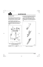
ONLY ONE HOUSING OPERATING
1. Determine which housing is not operating by
closing all the switches and checking the
power at the wires leading to the solenoid
valves (front and rear).
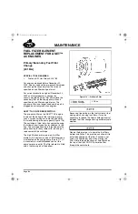
2. Remove the wire to the solenoid valve at the
cylinder head cover/spacer and check for
resistance (refer to the table on page 121).
No reading indicates an open circuit in the
wire or solenoid coil. A low resistance
reading indicates a short to ground in the
solenoid wire or solenoid coil.
A constant 12-volt low amperage signal is
supplied to the engine brake solenoids by the
V-MAC III module when the ignition switch is
turned on. During an engine braking event,
V-MAC increases the current to the solenoids to
activate the engine brake. The most accurate
method of checking electrical function of the
engine brake solenoid circuits is by using an
ammeter to measure current at the solenoids
when the engine brake is activated. When the
engine brake is activated, current should be
approximately 1.59 amps. For additional
information, consult the V-MAC
®
III Service
Manual, 8-211.
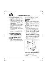
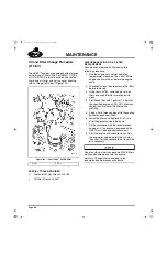
3. Test the solenoid by checking for current
draw and pull-in voltage per specifications
listed in the table on page 121.
J-TECH™ SOLENOID SPECIFICATIONS
INTERMITTENT BRAKING
Inspect all wiring for loose connections and all
switches for proper adjustment.
POOR PERFORMANCE
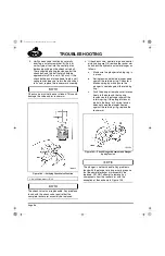
Connect a volt/ohmmeter (multimeter) to the
electrical connector on the valve cover/spacer.
Verify that a steady voltage signal is present
when the engine brake is active. If not, check for
loose connections or faulty switches. Repeat for
all valve cover/spacer terminals.
J-Tech™ Checks
(Hydraulic/Mechanical)
SPECIAL TOOL REQUIRED
앫
Jacobs Oil Pressure Test Kit 4559-18280
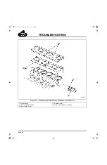
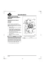
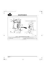
Remove the covers to begin inspecting the brake
components, including housings and attendant
hardware.
GENERAL INSPECTION AND ADJUSTMENT
VERIFICATION
1. Visually inspect the brake units for obvious
damage or missing parts. Replace as
necessary.
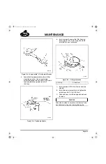
2. Check the slave piston-to-actuator pin for
proper clearance as shown in the table on
page 122. Also check the intake and
exhaust valve clearance. Readjust if
necessary.
Valve clearance must be checked with the timing
pointer hole on the flywheel housing aligned with
the proper valve setting mark on the flywheel for
the cylinder being checked. This ensures that the
valve lifter is on the camshaft base circle and not
on the brake ramp portion of the lobe.
Wear eye protection and do not expose your
face over the engine area. Keep hands away
from moving parts. Take precautions to
prevent oil leakage down onto the engine.
Whenever engine is running and the valve
covers are removed, oil splashing in the
engine brake area could cause personal
injury.
Never remove any engine brake component
with the engine running. Personal injury may
result.
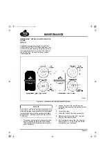
12-Volt Solenoid
—
Resistance: 8.7 to 10.0 ohms
—
Current Draw: 0.9 to 1.6 amps
—
Pull In Voltage: 9 volts DC minimum
24-Volt Solenoid
—
Resistance: 32.6 to 39.8 ohms
—
Current Draw: 0.46 to 0.75 amps
—
Pull In Voltage: 18 volts DC minimum
5-111.bk Page 121 Monday, July 10, 2006 2:26 PM
Содержание ASET AC
Страница 6: ...TABLE OF CONTENTS Page iii TABLE OF CONTENTS 5 111 bk Page iii Monday July 10 2006 2 26 PM...
Страница 14: ...INTRODUCTION Page 1 INTRODUCTION 5 111 bk Page 1 Monday July 10 2006 2 26 PM...
Страница 23: ...Page 10 NOTES 5 111 bk Page 10 Monday July 10 2006 2 26 PM...
Страница 24: ...VISUAL IDENTIFICATION Page 11 VISUAL IDENTIFICATION 5 111 bk Page 11 Monday July 10 2006 2 26 PM...
Страница 28: ...DESCRIPTION AND OPERATION Page 15 DESCRIPTION AND OPERATION 5 111 bk Page 15 Monday July 10 2006 2 26 PM...
Страница 96: ...COMPONENT LOCATOR Page 83 COMPONENT LOCATOR 5 111 bk Page 83 Monday July 10 2006 2 26 PM...
Страница 99: ...Page 86 NOTES 5 111 bk Page 86 Monday July 10 2006 2 26 PM...
Страница 100: ...TROUBLESHOOTING Page 87 TROUBLESHOOTING 5 111 bk Page 87 Monday July 10 2006 2 26 PM...
Страница 140: ...MAINTENANCE Page 127 MAINTENANCE 5 111 bk Page 127 Monday July 10 2006 2 26 PM...
Страница 153: ...Page 140 NOTES 5 111 bk Page 140 Monday July 10 2006 2 26 PM...
Страница 154: ...REPAIR INSTRUCTIONS PART 1 Page 141 REPAIR INSTRUCTIONS PART 1 5 111 bk Page 141 Monday July 10 2006 2 26 PM...
Страница 383: ...Page 370 NOTES 5 111 bk Page 370 Monday July 10 2006 2 26 PM...
Страница 384: ...REPAIR INSTRUCTIONS PART 2 Page 371 REPAIR INSTRUCTIONS PART 2 5 111 bk Page 371 Monday July 10 2006 2 26 PM...
Страница 454: ...REPAIR INSTRUCTIONS PART 3 Page 441 REPAIR INSTRUCTIONS PART 3 5 111 bk Page 441 Monday July 10 2006 2 26 PM...
Страница 479: ...Page 466 NOTES 5 111 bk Page 466 Monday July 10 2006 2 26 PM...
Страница 480: ...SPECIFICATIONS Page 467 SPECIFICATIONS 5 111 bk Page 467 Monday July 10 2006 2 26 PM...
Страница 505: ...Page 492 NOTES 5 111 bk Page 492 Monday July 10 2006 2 26 PM...
Страница 506: ...SCHEMATIC ROUTING DIAGRAMS Page 493 SCHEMATIC ROUTING DIAGRAMS 5 111 bk Page 493 Monday July 10 2006 2 26 PM...
Страница 513: ...Page 500 NOTES 5 111 bk Page 500 Monday July 10 2006 2 26 PM...
Страница 514: ...SPECIAL TOOLS EQUIPMENT Page 501 SPECIAL TOOLS EQUIPMENT 5 111 bk Page 501 Monday July 10 2006 2 26 PM...
Страница 519: ...Page 506 NOTES 5 111 bk Page 506 Monday July 10 2006 2 26 PM...
Страница 520: ...APPENDIX Page 507 APPENDIX 5 111 bk Page 507 Monday July 10 2006 2 26 PM...
Страница 528: ...INDEX Page 515 INDEX Index fm Page 515 Monday July 10 2006 2 48 PM...
Страница 535: ...Page 522 NOTES Index fm Page 522 Monday July 10 2006 2 48 PM...