


REPAIR INSTRUCTIONS, PART 2
Page 421
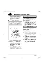
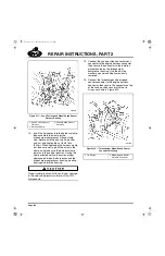
4. Reinstall the non-current design EECU
cooling plate as follows:
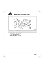
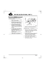
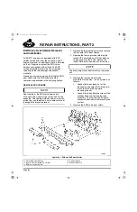
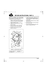
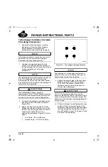
Non-Current Cooling Plate Design
The EECU cooling plate used on ASET™
AC engines from the beginning of production
through mid-May 2003 has two 0.580-inch
(14.7 mm) diameter mounting holes at the
lower corners of the plate. The lower
mounting isolators are installed through
these holes, and each isolator is then
secured with two 0.188-inch thick washers
and one nut.
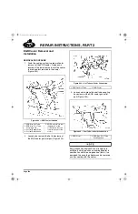
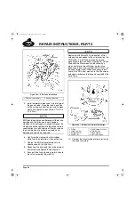
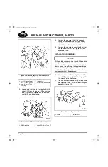
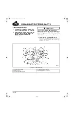
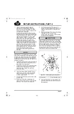
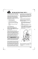
Due to tolerance stack-up between the
thickness of the cooling plate and the
dimensions of the isolators, some isolators
may not clamp onto the cooling plate when
the nut is tightened. When this occurs,
tightening the nut further will cause the
washers to rotate, which places force on the
rubber portion of the isolator, resulting in
tearing or breaking of the rubber. To prevent
this from occurring, it is recommended that
another washer (part No. 35A1446X) be
added between the two 0.188-inch washers.
This should be done whenever the EECU or
cooling plate is removed for any reason, or if
torn or broken mounting isolators are
encountered.
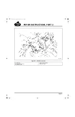
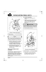
a.
For the non-current cooling plate
design, upper isolators are secured
with flanged nuts only; washers are not
used. The upper mounting nuts must
be tightened to 108 lb-in (12 N
폷
m).
b.
Non-current lower mounting nuts must
be tightened to 180 lb-in (20 N
폷
m).
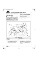
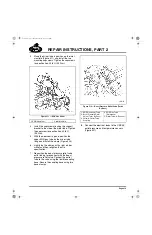
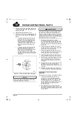
5. Reinstall the current design EECU cooling
plate as follows:
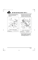
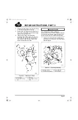
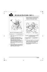
Current Cooling Plate Design
Beginning 5/15/03, the EECU cooling plate
arrangement used on the ASET™ AC
engines was changed to include integral
bushings at the two lower mounting bolt
holes. The lower mounting isolators are
installed through these bushings and
secured by one 0.065-inch thick washer and
one nut.
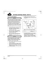
a.
For the current cooling plate design,
upper isolators are secured with
flanged nuts only; washers are not
used. The upper mounting nuts must
be tightened to 108 lb-in (12 N
폷
m).
b.
Current design lower mounting nuts
must be tightened to 180 lb-in (20 N
폷
m).
Final Assembly
Reinstall all accessory items, ducting, etc., that
were removed to gain access to the EGR
components. Replace all fluids drained from the
engine and reconnect the batteries.
5-111.bk Page 421 Monday, July 10, 2006 2:26 PM
Содержание ASET AC
Страница 6: ...TABLE OF CONTENTS Page iii TABLE OF CONTENTS 5 111 bk Page iii Monday July 10 2006 2 26 PM...
Страница 14: ...INTRODUCTION Page 1 INTRODUCTION 5 111 bk Page 1 Monday July 10 2006 2 26 PM...
Страница 23: ...Page 10 NOTES 5 111 bk Page 10 Monday July 10 2006 2 26 PM...
Страница 24: ...VISUAL IDENTIFICATION Page 11 VISUAL IDENTIFICATION 5 111 bk Page 11 Monday July 10 2006 2 26 PM...
Страница 28: ...DESCRIPTION AND OPERATION Page 15 DESCRIPTION AND OPERATION 5 111 bk Page 15 Monday July 10 2006 2 26 PM...
Страница 96: ...COMPONENT LOCATOR Page 83 COMPONENT LOCATOR 5 111 bk Page 83 Monday July 10 2006 2 26 PM...
Страница 99: ...Page 86 NOTES 5 111 bk Page 86 Monday July 10 2006 2 26 PM...
Страница 100: ...TROUBLESHOOTING Page 87 TROUBLESHOOTING 5 111 bk Page 87 Monday July 10 2006 2 26 PM...
Страница 140: ...MAINTENANCE Page 127 MAINTENANCE 5 111 bk Page 127 Monday July 10 2006 2 26 PM...
Страница 153: ...Page 140 NOTES 5 111 bk Page 140 Monday July 10 2006 2 26 PM...
Страница 154: ...REPAIR INSTRUCTIONS PART 1 Page 141 REPAIR INSTRUCTIONS PART 1 5 111 bk Page 141 Monday July 10 2006 2 26 PM...
Страница 383: ...Page 370 NOTES 5 111 bk Page 370 Monday July 10 2006 2 26 PM...
Страница 384: ...REPAIR INSTRUCTIONS PART 2 Page 371 REPAIR INSTRUCTIONS PART 2 5 111 bk Page 371 Monday July 10 2006 2 26 PM...
Страница 454: ...REPAIR INSTRUCTIONS PART 3 Page 441 REPAIR INSTRUCTIONS PART 3 5 111 bk Page 441 Monday July 10 2006 2 26 PM...
Страница 479: ...Page 466 NOTES 5 111 bk Page 466 Monday July 10 2006 2 26 PM...
Страница 480: ...SPECIFICATIONS Page 467 SPECIFICATIONS 5 111 bk Page 467 Monday July 10 2006 2 26 PM...
Страница 505: ...Page 492 NOTES 5 111 bk Page 492 Monday July 10 2006 2 26 PM...
Страница 506: ...SCHEMATIC ROUTING DIAGRAMS Page 493 SCHEMATIC ROUTING DIAGRAMS 5 111 bk Page 493 Monday July 10 2006 2 26 PM...
Страница 513: ...Page 500 NOTES 5 111 bk Page 500 Monday July 10 2006 2 26 PM...
Страница 514: ...SPECIAL TOOLS EQUIPMENT Page 501 SPECIAL TOOLS EQUIPMENT 5 111 bk Page 501 Monday July 10 2006 2 26 PM...
Страница 519: ...Page 506 NOTES 5 111 bk Page 506 Monday July 10 2006 2 26 PM...
Страница 520: ...APPENDIX Page 507 APPENDIX 5 111 bk Page 507 Monday July 10 2006 2 26 PM...
Страница 528: ...INDEX Page 515 INDEX Index fm Page 515 Monday July 10 2006 2 48 PM...
Страница 535: ...Page 522 NOTES Index fm Page 522 Monday July 10 2006 2 48 PM...