


Page 122
TROUBLESHOOTING
Brake slave piston clearance settings must be
made with the engine stopped and cold and with
the exhaust valves closed.
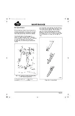
BRAKE SLAVE PISTON CLEARANCE SETTING
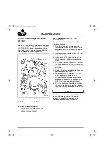
DETERMINING ENGINE OIL PRESSURE AND
OIL PRESSURE AT THE ENGINE BRAKE
UNITS
The engine brake requires a minimum oil
pressure to operate. The oil pressure reading on
the dash gauge is approximately the same as oil
pressure at the engine brake. The exception to
this is pre-2002 engines with Jake™ brake and
without external oil supply lines to the Jake
brakes. On these engines the oil pressure at the
Jake brake is approximately 15 psi less than the
dash gauge.
When determining minimum oil pressure, the oil
temperature must be at least 200
°
F (93
°
C) when
the test is performed. The pressure reading from
the dashboard oil pressure gauge is sufficient.
OIL PRESSURE REQUIREMENTS
If the oil pressure remains low, correct the engine
problem as described under “OIL PRESSURE
DROPPING BELOW MINIMUM REQUIRED FOR
ENGINE BRAKE OPERATION” in the
Troubleshooting Guide included in this section.
INSPECTION OF J-TECH™ ENGINE BRAKE
COMPONENTS
If oil pressure at the brake housings is sufficient
for brake operation, then inspect the engine
brake components for excess wear, damage or
malfunctioning conditions described in this
section.
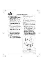
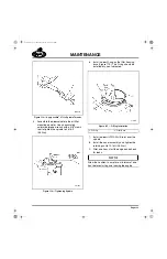
1. Start the engine and allow it to idle for a few
minutes. Check for oil leakage at the oil
supply screw, solenoid valve and housing
pipe plugs. Oil leakage can result in weak,
intermittent or no braking. If leakage is
found, shut down the engine and replace
seals or repair as needed.
When the engine is shut down for several
minutes, the oil in the brake housings will
bleed down. To refill the brake housings for
immediate operation, depress the solenoid
cap (pin) several times to fill the housing
with engine oil.
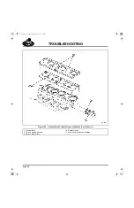
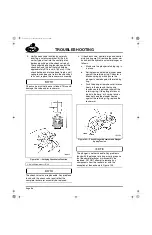
2. With the engine brake on, observe that the
master pistons are moving out of the
housing and making contact with the
exhaust rocker spherical nuts. They should
move in and out freely. If they do not, shut
down the engine and check the control
valves and control valve springs for those
cylinders.
Remove control valve retaining components
carefully to avoid personal injury. Control
valve retaining components are under load
from the control valve springs.
3. The control valve must move freely in the
bore. If not, remove it and replace with a
new
control valve.
If the bore is damaged (scored), use a light
crocus cloth to smooth the bore. Clean the bore
and install a
new
control valve. If severe damage
to the bore is found, replace the housing.
4. Replace any broken springs.
J-Tech™ Engine Brake
—
Adjustment: 0.021 inches (0.533 mm)
—
Slave piston adjusting tool: standard feeler gauge
—
Adjust following the firing order: 1, 5, 3, 6, 2, 4
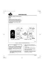
J-Tech™ Engine Brake
—
Engine rpm 2100: 40 psi (2.8 bar)
—
Engine rpm 1700: 35 psi (2.4 bar)*
—
Engine rpm 1500: 30 psi (2.0 bar)*
—
Engine rpm 1300: 30 psi (2.0 bar)*
—
Engine rpm 1100: 30 psi (2.0 bar)*
* Specified pressures with engine at 200
°
F (93
°
C)
minimum oil temperature.
5-111.bk Page 122 Monday, July 10, 2006 2:26 PM
Содержание ASET AC
Страница 6: ...TABLE OF CONTENTS Page iii TABLE OF CONTENTS 5 111 bk Page iii Monday July 10 2006 2 26 PM...
Страница 14: ...INTRODUCTION Page 1 INTRODUCTION 5 111 bk Page 1 Monday July 10 2006 2 26 PM...
Страница 23: ...Page 10 NOTES 5 111 bk Page 10 Monday July 10 2006 2 26 PM...
Страница 24: ...VISUAL IDENTIFICATION Page 11 VISUAL IDENTIFICATION 5 111 bk Page 11 Monday July 10 2006 2 26 PM...
Страница 28: ...DESCRIPTION AND OPERATION Page 15 DESCRIPTION AND OPERATION 5 111 bk Page 15 Monday July 10 2006 2 26 PM...
Страница 96: ...COMPONENT LOCATOR Page 83 COMPONENT LOCATOR 5 111 bk Page 83 Monday July 10 2006 2 26 PM...
Страница 99: ...Page 86 NOTES 5 111 bk Page 86 Monday July 10 2006 2 26 PM...
Страница 100: ...TROUBLESHOOTING Page 87 TROUBLESHOOTING 5 111 bk Page 87 Monday July 10 2006 2 26 PM...
Страница 140: ...MAINTENANCE Page 127 MAINTENANCE 5 111 bk Page 127 Monday July 10 2006 2 26 PM...
Страница 153: ...Page 140 NOTES 5 111 bk Page 140 Monday July 10 2006 2 26 PM...
Страница 154: ...REPAIR INSTRUCTIONS PART 1 Page 141 REPAIR INSTRUCTIONS PART 1 5 111 bk Page 141 Monday July 10 2006 2 26 PM...
Страница 383: ...Page 370 NOTES 5 111 bk Page 370 Monday July 10 2006 2 26 PM...
Страница 384: ...REPAIR INSTRUCTIONS PART 2 Page 371 REPAIR INSTRUCTIONS PART 2 5 111 bk Page 371 Monday July 10 2006 2 26 PM...
Страница 454: ...REPAIR INSTRUCTIONS PART 3 Page 441 REPAIR INSTRUCTIONS PART 3 5 111 bk Page 441 Monday July 10 2006 2 26 PM...
Страница 479: ...Page 466 NOTES 5 111 bk Page 466 Monday July 10 2006 2 26 PM...
Страница 480: ...SPECIFICATIONS Page 467 SPECIFICATIONS 5 111 bk Page 467 Monday July 10 2006 2 26 PM...
Страница 505: ...Page 492 NOTES 5 111 bk Page 492 Monday July 10 2006 2 26 PM...
Страница 506: ...SCHEMATIC ROUTING DIAGRAMS Page 493 SCHEMATIC ROUTING DIAGRAMS 5 111 bk Page 493 Monday July 10 2006 2 26 PM...
Страница 513: ...Page 500 NOTES 5 111 bk Page 500 Monday July 10 2006 2 26 PM...
Страница 514: ...SPECIAL TOOLS EQUIPMENT Page 501 SPECIAL TOOLS EQUIPMENT 5 111 bk Page 501 Monday July 10 2006 2 26 PM...
Страница 519: ...Page 506 NOTES 5 111 bk Page 506 Monday July 10 2006 2 26 PM...
Страница 520: ...APPENDIX Page 507 APPENDIX 5 111 bk Page 507 Monday July 10 2006 2 26 PM...
Страница 528: ...INDEX Page 515 INDEX Index fm Page 515 Monday July 10 2006 2 48 PM...
Страница 535: ...Page 522 NOTES Index fm Page 522 Monday July 10 2006 2 48 PM...