


Page 104
TROUBLESHOOTING
CYLINDER HEAD AND
CYLINDER BLOCK LEAK TEST
PROCEDURE
Verify suspected leaks in the cylinder heads or
cylinder block by pressure testing before deciding
to replace the cylinder head or block. Do not use
magnaflux inspections alone as replacement
criteria.
Before proceeding with the tests, look for coolant
stains around the 3/4-inch NPT plugs on the tops
of the cylinder heads. Check that the plugs are
torqued to 55 lb-ft (75 N
폷
m).
Cylinder head pipe plugs used on engines
manufactured April 1, 1999 or later (beginning
with engine serial number series 9F) have
encapsulated epoxy sealant applied to the
threads. These pipe plugs are tightened to
55 lb-ft (75 N
폷
m) at assembly, and the epoxy
locks them in place. These plugs will not turn
when an attempt is made to tighten them. If a
coolant leak at an epoxy-sealed pipe plug is
suspected, the plug may be removed by heating it
to 400
°
F (205
°
C) with a torch. Before reinstalling
the plug, the epoxy sealant must be thoroughly
cleaned from the pipe plug threads, and the
threads in the cylinder head. The plug and the
cylinder head threads must then be cleaned with
Loctite
®
Primer T and resealed with Loctite
®
277.
Reinstall the plug and torque to 55 lb-ft (75 N
폷
m).
Also, make sure leakage is not caused by the oil
cooler or air compressor. Perform the simpler
checks first to prevent unnecessary engine
disassembly. While performing the following
tests, watch for indications of minor leaks, such
as small bubbles, that can develop into more
severe leaks during engine operation.
Cylinder Head and Head Gasket
Check — In Chassis
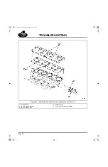
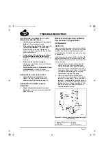
1. Look for coolant stains around the 3/4-inch
NPT pipe plugs on top of the cylinder heads.
Check plug torque. The plug torque
specification is 55 lb-ft (75 N
폷
m). Refer to
Figure 98.
98
Figure 98 — Cylinder Head Pipe Plugs (3/4-Inch NPT)
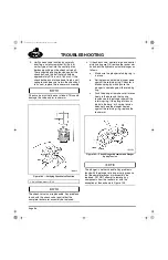
2. Before removing the thermostat(s), drain
coolant from the cooling system until the
coolant level is below the thermostat
housing.
3. Remove the thermostat(s) and leave the
thermostat housing open. Install a short
section of hose, approximately 6–8 inches
(152–203 mm) long, on the thermostat
housing and add enough coolant to fill the
housing.
4. Remove the fan belt from the water pump.
5. Start the engine and run at 1,000 rpm.
6. Observe coolant in the thermostat housing
for air bubbles. This can indicate combustion
pressurization of the cooling system and
possible cylinder head gasket failure. Also,
watch for traces of oil which would indicate
possible cylinder head gasket or oil passage
leakage.
1. Cylinder Head
2. Pipe Plugs
5-111.bk Page 104 Monday, July 10, 2006 2:26 PM
Содержание ASET AC
Страница 6: ...TABLE OF CONTENTS Page iii TABLE OF CONTENTS 5 111 bk Page iii Monday July 10 2006 2 26 PM...
Страница 14: ...INTRODUCTION Page 1 INTRODUCTION 5 111 bk Page 1 Monday July 10 2006 2 26 PM...
Страница 23: ...Page 10 NOTES 5 111 bk Page 10 Monday July 10 2006 2 26 PM...
Страница 24: ...VISUAL IDENTIFICATION Page 11 VISUAL IDENTIFICATION 5 111 bk Page 11 Monday July 10 2006 2 26 PM...
Страница 28: ...DESCRIPTION AND OPERATION Page 15 DESCRIPTION AND OPERATION 5 111 bk Page 15 Monday July 10 2006 2 26 PM...
Страница 96: ...COMPONENT LOCATOR Page 83 COMPONENT LOCATOR 5 111 bk Page 83 Monday July 10 2006 2 26 PM...
Страница 99: ...Page 86 NOTES 5 111 bk Page 86 Monday July 10 2006 2 26 PM...
Страница 100: ...TROUBLESHOOTING Page 87 TROUBLESHOOTING 5 111 bk Page 87 Monday July 10 2006 2 26 PM...
Страница 140: ...MAINTENANCE Page 127 MAINTENANCE 5 111 bk Page 127 Monday July 10 2006 2 26 PM...
Страница 153: ...Page 140 NOTES 5 111 bk Page 140 Monday July 10 2006 2 26 PM...
Страница 154: ...REPAIR INSTRUCTIONS PART 1 Page 141 REPAIR INSTRUCTIONS PART 1 5 111 bk Page 141 Monday July 10 2006 2 26 PM...
Страница 383: ...Page 370 NOTES 5 111 bk Page 370 Monday July 10 2006 2 26 PM...
Страница 384: ...REPAIR INSTRUCTIONS PART 2 Page 371 REPAIR INSTRUCTIONS PART 2 5 111 bk Page 371 Monday July 10 2006 2 26 PM...
Страница 454: ...REPAIR INSTRUCTIONS PART 3 Page 441 REPAIR INSTRUCTIONS PART 3 5 111 bk Page 441 Monday July 10 2006 2 26 PM...
Страница 479: ...Page 466 NOTES 5 111 bk Page 466 Monday July 10 2006 2 26 PM...
Страница 480: ...SPECIFICATIONS Page 467 SPECIFICATIONS 5 111 bk Page 467 Monday July 10 2006 2 26 PM...
Страница 505: ...Page 492 NOTES 5 111 bk Page 492 Monday July 10 2006 2 26 PM...
Страница 506: ...SCHEMATIC ROUTING DIAGRAMS Page 493 SCHEMATIC ROUTING DIAGRAMS 5 111 bk Page 493 Monday July 10 2006 2 26 PM...
Страница 513: ...Page 500 NOTES 5 111 bk Page 500 Monday July 10 2006 2 26 PM...
Страница 514: ...SPECIAL TOOLS EQUIPMENT Page 501 SPECIAL TOOLS EQUIPMENT 5 111 bk Page 501 Monday July 10 2006 2 26 PM...
Страница 519: ...Page 506 NOTES 5 111 bk Page 506 Monday July 10 2006 2 26 PM...
Страница 520: ...APPENDIX Page 507 APPENDIX 5 111 bk Page 507 Monday July 10 2006 2 26 PM...
Страница 528: ...INDEX Page 515 INDEX Index fm Page 515 Monday July 10 2006 2 48 PM...
Страница 535: ...Page 522 NOTES Index fm Page 522 Monday July 10 2006 2 48 PM...