REPAIR INSTRUCTIONS, PART 1
Page 223
CONNECTING ROD AND
PISTON BENCH PROCEDURES
Connecting Rod Inspection and
Reconditioning
[212 LP]
GENERAL INSTRUCTIONS
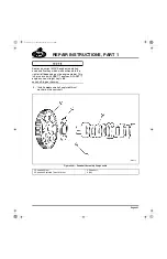
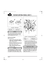
Each connecting rod assembly has two alignment
sleeves, one sleeve in each capscrew hole of the
rod cap to locate and align the cap and rod thrust
faces (Figure 230). These sleeves provide the
best alignment when the sleeve gaps are
positioned at a location approximately 90 degrees
to the tongue or groove. The sleeve gaps MUST
NOT be in line with the tongue or groove.
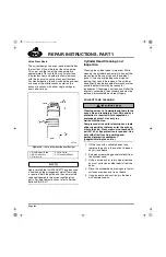
230
Figure 230 — Connecting Rod with Alignment Sleeves
It is essential to closely control the weight of
reciprocating parts. Connecting rods fall into two
weight classes, M1 or M2. Initially, the classes
were identified by the respective “M” number (M1
or M2) stamped onto the connecting rod bearing
cap. Now, however, only the M1 rod carries the
weight class identification stamped on the rod
cap. The M2 connecting rod is no longer stamped
with the weight class identifier.
When installing a single rod, or less than a full
set, examine the removed rod(s) for part number
and M number. Installing parts with the same
weight class is preferred.
Connecting rods can be weighed to ensure that
the proper weight class is used. Connecting rod
weights for an engine should not vary by more
than 0.46 ounce (13.04 grams) within each
weight class.
The maximum weight difference between the
heaviest possible M2 rod and the lightest
possible M1 rod is 0.83 ounce (23.53 grams).
SPECIAL TOOLS REQUIRED
앫
Piston Pin Bushing Remover/Installer
J 37717
앫
Piston Pin Burnishing Broach J 37718
앫
Connecting Rod Fixture 945-6041
INSPECTION
Inspect each connecting rod for the following
conditions. If any rod(s) is suspected of being
faulty, replace it.
앫
Inspect the rods for nicks, cracks, signs of
overheating, bends or twisting that can
cause rod failure.
앫
Inspect the bolt holes for elongation or
pulled threads.
앫
Check the mating surfaces between the rod
and cap for correct fit.
앫
Inspect the crankshaft journal bearing
surface of each rod and wrist pin bushing.
If it is determined that the condition of any part or
component is questionable or is at the limit of
tolerance, replace it. If the questionable part or
component is reused, it may fail or become out of
tolerance after a short time in operation. It is
cost-efficient to replace any questionable items
when rebuilding.
Use genuine MACK replacement parts.
1. Rod Cap
2. Bearing Insert
3. Alignment Sleeve
5-111.bk Page 223 Monday, July 10, 2006 2:26 PM
Содержание ASET AC
Страница 6: ...TABLE OF CONTENTS Page iii TABLE OF CONTENTS 5 111 bk Page iii Monday July 10 2006 2 26 PM...
Страница 14: ...INTRODUCTION Page 1 INTRODUCTION 5 111 bk Page 1 Monday July 10 2006 2 26 PM...
Страница 23: ...Page 10 NOTES 5 111 bk Page 10 Monday July 10 2006 2 26 PM...
Страница 24: ...VISUAL IDENTIFICATION Page 11 VISUAL IDENTIFICATION 5 111 bk Page 11 Monday July 10 2006 2 26 PM...
Страница 28: ...DESCRIPTION AND OPERATION Page 15 DESCRIPTION AND OPERATION 5 111 bk Page 15 Monday July 10 2006 2 26 PM...
Страница 96: ...COMPONENT LOCATOR Page 83 COMPONENT LOCATOR 5 111 bk Page 83 Monday July 10 2006 2 26 PM...
Страница 99: ...Page 86 NOTES 5 111 bk Page 86 Monday July 10 2006 2 26 PM...
Страница 100: ...TROUBLESHOOTING Page 87 TROUBLESHOOTING 5 111 bk Page 87 Monday July 10 2006 2 26 PM...
Страница 140: ...MAINTENANCE Page 127 MAINTENANCE 5 111 bk Page 127 Monday July 10 2006 2 26 PM...
Страница 153: ...Page 140 NOTES 5 111 bk Page 140 Monday July 10 2006 2 26 PM...
Страница 154: ...REPAIR INSTRUCTIONS PART 1 Page 141 REPAIR INSTRUCTIONS PART 1 5 111 bk Page 141 Monday July 10 2006 2 26 PM...
Страница 383: ...Page 370 NOTES 5 111 bk Page 370 Monday July 10 2006 2 26 PM...
Страница 384: ...REPAIR INSTRUCTIONS PART 2 Page 371 REPAIR INSTRUCTIONS PART 2 5 111 bk Page 371 Monday July 10 2006 2 26 PM...
Страница 454: ...REPAIR INSTRUCTIONS PART 3 Page 441 REPAIR INSTRUCTIONS PART 3 5 111 bk Page 441 Monday July 10 2006 2 26 PM...
Страница 479: ...Page 466 NOTES 5 111 bk Page 466 Monday July 10 2006 2 26 PM...
Страница 480: ...SPECIFICATIONS Page 467 SPECIFICATIONS 5 111 bk Page 467 Monday July 10 2006 2 26 PM...
Страница 505: ...Page 492 NOTES 5 111 bk Page 492 Monday July 10 2006 2 26 PM...
Страница 506: ...SCHEMATIC ROUTING DIAGRAMS Page 493 SCHEMATIC ROUTING DIAGRAMS 5 111 bk Page 493 Monday July 10 2006 2 26 PM...
Страница 513: ...Page 500 NOTES 5 111 bk Page 500 Monday July 10 2006 2 26 PM...
Страница 514: ...SPECIAL TOOLS EQUIPMENT Page 501 SPECIAL TOOLS EQUIPMENT 5 111 bk Page 501 Monday July 10 2006 2 26 PM...
Страница 519: ...Page 506 NOTES 5 111 bk Page 506 Monday July 10 2006 2 26 PM...
Страница 520: ...APPENDIX Page 507 APPENDIX 5 111 bk Page 507 Monday July 10 2006 2 26 PM...
Страница 528: ...INDEX Page 515 INDEX Index fm Page 515 Monday July 10 2006 2 48 PM...
Страница 535: ...Page 522 NOTES Index fm Page 522 Monday July 10 2006 2 48 PM...


