


Page 278
REPAIR INSTRUCTIONS, PART 1
REASSEMBLY
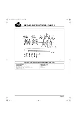
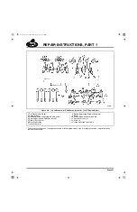
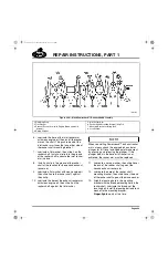
Refer back to Figure 306.
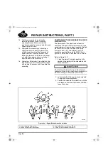
1. Install the one-piece pump gear/shaft and
thrust washer in the housing and check for
free spin.
2. Install the key in the pump gear shaft.
3. Place the driven gear on the shaft, aligning
the slot with the shaft key. Then, press the
driven gear onto the shaft.
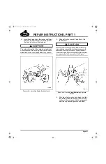
4. Install the washer and self-locking nut on the
shaft. Tighten the nut to specification,
60 lb-ft (81 N
폷
m), using torque wrench
J 24407, or equivalent.
5. Install the idler gear on the housing shaft.
6. Apply Loctite
®
271 to the threads of the
cover capscrews and install the cover.
Tighten the capscrews to specification,
15 lb-ft (20 N
폷
m).
7. Install the oil pressure relief valve plunger in
the relief valve housing.
To maintain correct oil pressure for the various oil
system arrangements, the proper oil pressure
relief valve spring and cap combination must be
used. Using incorrect components may result in
either high or low oil pressure, and contribute to
premature engine damage.
8. Install the oil pressure relief valve spring in
the relief valve housing.
9. Clean the relief valve cap and pressure relief
spacers (if equipped with spacers at
disassembly). Install the spacers over the
cap threads (if required for cold pressure
relief) and install the cap in the bore of the oil
pump housing cover. Tighten the pressure
relief cap to specifications.
10. Apply Loctite
®
271 to the threads of the
pump inlet flange plate capscrews. Install
the flange plate and gasket on the housing
and secure the flange plate with the
capscrews.
11. Apply Loctite
®
271 to the threads of the oil
inlet (pickup) tube capscrews. Install the
inlet tube and screen assembly. Secure the
assembly with the capscrews.
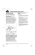
Because the inlet tube must be in a vertical
position when installed in the engine, the
mounting flange bolt pattern is offset to the same
degree as the oil pump-to-cylinder block
mounting angle. The mounting flange of the inlet
tube has four bolt holes marked with an “F” or “R”
to distinguish which two holes are used for the
front sump, and which two holes are used for rear
sump applications. Caution must be used to
ensure that the correct mounting holes are used
for the proper sump applications.
5-111.bk Page 278 Monday, July 10, 2006 2:26 PM
Содержание ASET AC
Страница 6: ...TABLE OF CONTENTS Page iii TABLE OF CONTENTS 5 111 bk Page iii Monday July 10 2006 2 26 PM...
Страница 14: ...INTRODUCTION Page 1 INTRODUCTION 5 111 bk Page 1 Monday July 10 2006 2 26 PM...
Страница 23: ...Page 10 NOTES 5 111 bk Page 10 Monday July 10 2006 2 26 PM...
Страница 24: ...VISUAL IDENTIFICATION Page 11 VISUAL IDENTIFICATION 5 111 bk Page 11 Monday July 10 2006 2 26 PM...
Страница 28: ...DESCRIPTION AND OPERATION Page 15 DESCRIPTION AND OPERATION 5 111 bk Page 15 Monday July 10 2006 2 26 PM...
Страница 96: ...COMPONENT LOCATOR Page 83 COMPONENT LOCATOR 5 111 bk Page 83 Monday July 10 2006 2 26 PM...
Страница 99: ...Page 86 NOTES 5 111 bk Page 86 Monday July 10 2006 2 26 PM...
Страница 100: ...TROUBLESHOOTING Page 87 TROUBLESHOOTING 5 111 bk Page 87 Monday July 10 2006 2 26 PM...
Страница 140: ...MAINTENANCE Page 127 MAINTENANCE 5 111 bk Page 127 Monday July 10 2006 2 26 PM...
Страница 153: ...Page 140 NOTES 5 111 bk Page 140 Monday July 10 2006 2 26 PM...
Страница 154: ...REPAIR INSTRUCTIONS PART 1 Page 141 REPAIR INSTRUCTIONS PART 1 5 111 bk Page 141 Monday July 10 2006 2 26 PM...
Страница 383: ...Page 370 NOTES 5 111 bk Page 370 Monday July 10 2006 2 26 PM...
Страница 384: ...REPAIR INSTRUCTIONS PART 2 Page 371 REPAIR INSTRUCTIONS PART 2 5 111 bk Page 371 Monday July 10 2006 2 26 PM...
Страница 454: ...REPAIR INSTRUCTIONS PART 3 Page 441 REPAIR INSTRUCTIONS PART 3 5 111 bk Page 441 Monday July 10 2006 2 26 PM...
Страница 479: ...Page 466 NOTES 5 111 bk Page 466 Monday July 10 2006 2 26 PM...
Страница 480: ...SPECIFICATIONS Page 467 SPECIFICATIONS 5 111 bk Page 467 Monday July 10 2006 2 26 PM...
Страница 505: ...Page 492 NOTES 5 111 bk Page 492 Monday July 10 2006 2 26 PM...
Страница 506: ...SCHEMATIC ROUTING DIAGRAMS Page 493 SCHEMATIC ROUTING DIAGRAMS 5 111 bk Page 493 Monday July 10 2006 2 26 PM...
Страница 513: ...Page 500 NOTES 5 111 bk Page 500 Monday July 10 2006 2 26 PM...
Страница 514: ...SPECIAL TOOLS EQUIPMENT Page 501 SPECIAL TOOLS EQUIPMENT 5 111 bk Page 501 Monday July 10 2006 2 26 PM...
Страница 519: ...Page 506 NOTES 5 111 bk Page 506 Monday July 10 2006 2 26 PM...
Страница 520: ...APPENDIX Page 507 APPENDIX 5 111 bk Page 507 Monday July 10 2006 2 26 PM...
Страница 528: ...INDEX Page 515 INDEX Index fm Page 515 Monday July 10 2006 2 48 PM...
Страница 535: ...Page 522 NOTES Index fm Page 522 Monday July 10 2006 2 48 PM...