


Page 512
APPENDIX
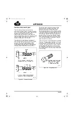
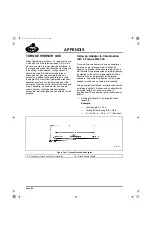
If it is not possible to see inside the manifold, a
piece of wire or similar object could be inserted
into the manifold and used to check if oil is
present. Accumulated oil can be removed with a
suction pump by removing the air compressor
boost pressure supply line and fitting located at
the rear of the manifold, then inserting a suction
pump hose into the opened port. Make sure the
hose extends all the way to the bottom of the
manifold. Using this method ensures that oil
accumulated at the rear of the manifold will be
removed.
In most instances, the engine is mounted in the
chassis tilted toward the rear. Because of this, oil
will collect at the back of the inlet manifold
making it possible for some oil to enter cylinder
No. 6. If enough oil enters the cylinder, hydraulic
lock could occur and result in severe damage
when attempting to start the engine. To avoid
such damage, use the barring tool to rotate the
engine several revolutions before starting.
Resistance felt as the engine is rotated (as
cylinder No. 6 approaches TDC of the
compression stroke), indicates that oil may be
present in the combustion chamber. To remove
this oil, remove the injection nozzle from cylinder
No. 6 and rotate the engine several more
revolutions to push the oil from the cylinder.
Before reinstalling the nozzle, clean the oil from
the nozzle hole in the cylinder head.
Cleaning Oil from the Charge Air
Cooler
Oil can be removed from the charge air cooler as
follows:
1. Remove the charge air cooler and flush the
inside with a safety solvent to remove oil and
other debris.
2. Shake the cooler from side-to-side to
remove large pieces.
3. Wash the cooler with hot, soapy water (use
liquid gel automatic dishwasher detergent to
minimize foaming). Rinse with clean water
and blow dry with compressed air in the
reverse direction of flow.
4. Carefully inspect the cooler to ensure
cleanliness.
Do not use caustic cleaners when flushing the
cooler. Be extremely careful when handling the
cooler so as not to damage the core.
When flushing the charge air cooler, it is
recommended that the cooler be turned upside
down and a reverse flow be used to flush the
inside.
If oil and debris are still evident inside the charge
air cooler after it has been thoroughly cleaned,
contact the Mack Trucks, Inc. Warranty
Department to authorize replacement.
Cleaning the Intake Air System
When a turbocharger fails, debris from the
compressor wheel and surrounding area has very
high inertia and can travel throughout the intake
air piping and into the air cleaner. Additionally,
small metal pieces resulting from the failure are
extremely hot and will melt into and stick to the
insides of the plastic hoses and tubing. All these
pieces must be removed from the intake air
system. Because the turbocharger wheels spin at
such high speeds, even a small piece of debris
can throw the wheels out of balance, resulting in
eventual failure of the replacement turbocharger.
The intake air ducts should be disassembled and
the insides of the ducts, elbows, hoses, etc.,
carefully checked for debris and cleaned as
necessary. The air filter element should also be
removed, inspected (be sure to check the inside
of the filter) and replaced as necessary.
Thoroughly clean the inside of the air cleaner
canister of any debris.
5-111.bk Page 512 Monday, July 10, 2006 2:26 PM
Содержание ASET AC
Страница 6: ...TABLE OF CONTENTS Page iii TABLE OF CONTENTS 5 111 bk Page iii Monday July 10 2006 2 26 PM...
Страница 14: ...INTRODUCTION Page 1 INTRODUCTION 5 111 bk Page 1 Monday July 10 2006 2 26 PM...
Страница 23: ...Page 10 NOTES 5 111 bk Page 10 Monday July 10 2006 2 26 PM...
Страница 24: ...VISUAL IDENTIFICATION Page 11 VISUAL IDENTIFICATION 5 111 bk Page 11 Monday July 10 2006 2 26 PM...
Страница 28: ...DESCRIPTION AND OPERATION Page 15 DESCRIPTION AND OPERATION 5 111 bk Page 15 Monday July 10 2006 2 26 PM...
Страница 96: ...COMPONENT LOCATOR Page 83 COMPONENT LOCATOR 5 111 bk Page 83 Monday July 10 2006 2 26 PM...
Страница 99: ...Page 86 NOTES 5 111 bk Page 86 Monday July 10 2006 2 26 PM...
Страница 100: ...TROUBLESHOOTING Page 87 TROUBLESHOOTING 5 111 bk Page 87 Monday July 10 2006 2 26 PM...
Страница 140: ...MAINTENANCE Page 127 MAINTENANCE 5 111 bk Page 127 Monday July 10 2006 2 26 PM...
Страница 153: ...Page 140 NOTES 5 111 bk Page 140 Monday July 10 2006 2 26 PM...
Страница 154: ...REPAIR INSTRUCTIONS PART 1 Page 141 REPAIR INSTRUCTIONS PART 1 5 111 bk Page 141 Monday July 10 2006 2 26 PM...
Страница 383: ...Page 370 NOTES 5 111 bk Page 370 Monday July 10 2006 2 26 PM...
Страница 384: ...REPAIR INSTRUCTIONS PART 2 Page 371 REPAIR INSTRUCTIONS PART 2 5 111 bk Page 371 Monday July 10 2006 2 26 PM...
Страница 454: ...REPAIR INSTRUCTIONS PART 3 Page 441 REPAIR INSTRUCTIONS PART 3 5 111 bk Page 441 Monday July 10 2006 2 26 PM...
Страница 479: ...Page 466 NOTES 5 111 bk Page 466 Monday July 10 2006 2 26 PM...
Страница 480: ...SPECIFICATIONS Page 467 SPECIFICATIONS 5 111 bk Page 467 Monday July 10 2006 2 26 PM...
Страница 505: ...Page 492 NOTES 5 111 bk Page 492 Monday July 10 2006 2 26 PM...
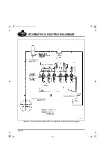
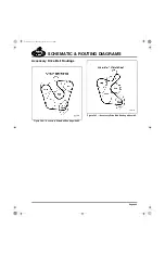
Страница 506: ...SCHEMATIC ROUTING DIAGRAMS Page 493 SCHEMATIC ROUTING DIAGRAMS 5 111 bk Page 493 Monday July 10 2006 2 26 PM...
Страница 513: ...Page 500 NOTES 5 111 bk Page 500 Monday July 10 2006 2 26 PM...
Страница 514: ...SPECIAL TOOLS EQUIPMENT Page 501 SPECIAL TOOLS EQUIPMENT 5 111 bk Page 501 Monday July 10 2006 2 26 PM...
Страница 519: ...Page 506 NOTES 5 111 bk Page 506 Monday July 10 2006 2 26 PM...
Страница 520: ...APPENDIX Page 507 APPENDIX 5 111 bk Page 507 Monday July 10 2006 2 26 PM...
Страница 528: ...INDEX Page 515 INDEX Index fm Page 515 Monday July 10 2006 2 48 PM...
Страница 535: ...Page 522 NOTES Index fm Page 522 Monday July 10 2006 2 48 PM...