Page 306
REPAIR INSTRUCTIONS, PART 1
2. Submerge the valve lifters into a container of
clean engine oil to allow oil to fill the
passages to the roller axles. Remove each
lifter and while holding it vertically, spin the
roller to make sure the oil flows to the
surfaces between the axle and roller. This
step is important to provide adequate
break-in to the axle and roller at initial
start-up of the engine.
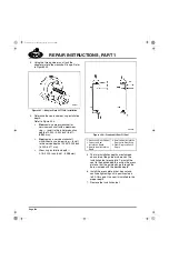
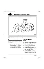
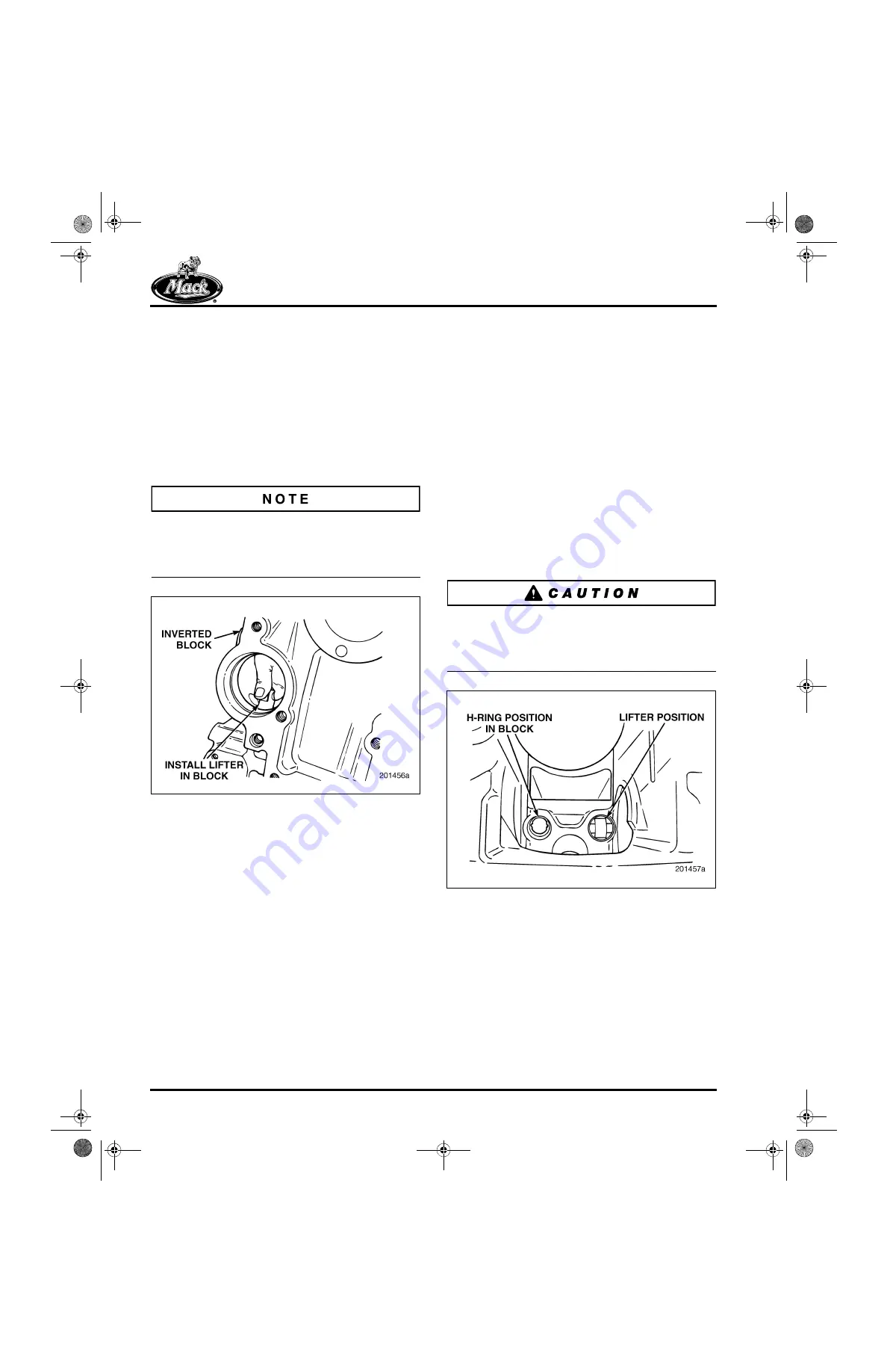
3. Install the lifters into the cylinder block lifter
bores as shown in Figure 348.
Used valve lifters
have established wear
patterns. Valve lifters being returned to service
should be installed in the same location from
which they were removed.
348
Figure 348 — Valve Lifter Installation
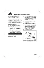
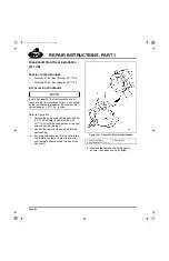
4. Install a lifter in the lifter bore by aligning the
lifter flats with the H-ring flats (Figure 349).
Use only light finger pressure when installing
the lifters. Verify that the lifter has complete
freedom of movement in the bore and H-ring
in both the upward and downward
directions. When the lifter is seated, it should
be possible to rotate it slightly from left to
right. If the lifter is sticky or tight, or if
additional force is required to install the lifter,
proceed as follows:
a.
If new lifters are being installed and the
fit is tight, try the lifter in another lifter
bore. A stack-up of component
tolerances can result in a lifter being
free in another bore. This is acceptable.
b.
If the original lifters are being reused
and the fit is tight, trial fit a
new
lifter(s)
in the bore. If the tightness persists, the
problem may be in the lifter bore or
H-ring. (Because of established wear
patterns, it is not recommended to
install a used lifter in any bore other
than the bore from which it was
removed.)
c.
If the problem is confined to a particular
bore, determine if the lifter tightness is
due to the lifter bore or the H-ring by
trial fitting another lifter. To correct the
problem condition, refer to the
procedure under “Salvaging a Valve
Lifter Bore” or “H-Ring Replacement” in
the CYLINDER BLOCK
RECONDITIONING section.
A lifter that does not move freely in the lifter bore
can be impacted by the cam lobe during engine
operation. This will result in damage or breakage
of the ceramic roller.
349
Figure 349 — Installed Valve Lifter
5-111.bk Page 306 Monday, July 10, 2006 2:26 PM
Содержание ASET AC
Страница 6: ...TABLE OF CONTENTS Page iii TABLE OF CONTENTS 5 111 bk Page iii Monday July 10 2006 2 26 PM...
Страница 14: ...INTRODUCTION Page 1 INTRODUCTION 5 111 bk Page 1 Monday July 10 2006 2 26 PM...
Страница 23: ...Page 10 NOTES 5 111 bk Page 10 Monday July 10 2006 2 26 PM...
Страница 24: ...VISUAL IDENTIFICATION Page 11 VISUAL IDENTIFICATION 5 111 bk Page 11 Monday July 10 2006 2 26 PM...
Страница 28: ...DESCRIPTION AND OPERATION Page 15 DESCRIPTION AND OPERATION 5 111 bk Page 15 Monday July 10 2006 2 26 PM...
Страница 96: ...COMPONENT LOCATOR Page 83 COMPONENT LOCATOR 5 111 bk Page 83 Monday July 10 2006 2 26 PM...
Страница 99: ...Page 86 NOTES 5 111 bk Page 86 Monday July 10 2006 2 26 PM...
Страница 100: ...TROUBLESHOOTING Page 87 TROUBLESHOOTING 5 111 bk Page 87 Monday July 10 2006 2 26 PM...
Страница 140: ...MAINTENANCE Page 127 MAINTENANCE 5 111 bk Page 127 Monday July 10 2006 2 26 PM...
Страница 153: ...Page 140 NOTES 5 111 bk Page 140 Monday July 10 2006 2 26 PM...
Страница 154: ...REPAIR INSTRUCTIONS PART 1 Page 141 REPAIR INSTRUCTIONS PART 1 5 111 bk Page 141 Monday July 10 2006 2 26 PM...
Страница 383: ...Page 370 NOTES 5 111 bk Page 370 Monday July 10 2006 2 26 PM...
Страница 384: ...REPAIR INSTRUCTIONS PART 2 Page 371 REPAIR INSTRUCTIONS PART 2 5 111 bk Page 371 Monday July 10 2006 2 26 PM...
Страница 454: ...REPAIR INSTRUCTIONS PART 3 Page 441 REPAIR INSTRUCTIONS PART 3 5 111 bk Page 441 Monday July 10 2006 2 26 PM...
Страница 479: ...Page 466 NOTES 5 111 bk Page 466 Monday July 10 2006 2 26 PM...
Страница 480: ...SPECIFICATIONS Page 467 SPECIFICATIONS 5 111 bk Page 467 Monday July 10 2006 2 26 PM...
Страница 505: ...Page 492 NOTES 5 111 bk Page 492 Monday July 10 2006 2 26 PM...
Страница 506: ...SCHEMATIC ROUTING DIAGRAMS Page 493 SCHEMATIC ROUTING DIAGRAMS 5 111 bk Page 493 Monday July 10 2006 2 26 PM...
Страница 513: ...Page 500 NOTES 5 111 bk Page 500 Monday July 10 2006 2 26 PM...
Страница 514: ...SPECIAL TOOLS EQUIPMENT Page 501 SPECIAL TOOLS EQUIPMENT 5 111 bk Page 501 Monday July 10 2006 2 26 PM...
Страница 519: ...Page 506 NOTES 5 111 bk Page 506 Monday July 10 2006 2 26 PM...
Страница 520: ...APPENDIX Page 507 APPENDIX 5 111 bk Page 507 Monday July 10 2006 2 26 PM...
Страница 528: ...INDEX Page 515 INDEX Index fm Page 515 Monday July 10 2006 2 48 PM...
Страница 535: ...Page 522 NOTES Index fm Page 522 Monday July 10 2006 2 48 PM...


