Page 58
DESCRIPTION AND OPERATION
ROCKER ARM AND SHAFT ASSEMBLY
Rocker Arm Improvements Effective January
2002
Effective with the January 2002 introduction of
the spring-loaded push rods, both inlet and
exhaust both inlet and exhaust rocker arms have
been revised to provide pressure oil feed to the
valve adjusting screws. A vertical groove has
been added to the inboard side of the adjusting
screw bore, from the top of the bore to the oil
supply hole that is just above the bottom of the
bore. On the outboard side of the rocker arm
adjusting screw boss, a closure plug has been
installed into the drilled hole to eliminate the leak
path for pressure oil and ensure sufficient oil to
the adjusting screw.
64
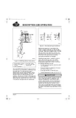
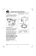
Figure 64 — Rocker Arm Effective January 2002
Further rocker arm improvements include
adjusting screws that have a groove around the
center of the screw, an oil passage cross-drilled
through the shank of the screw and an oil
passage drilled along the vertical center line of
the screw. These oil passages provide lubrication
to the ball end of the adjusting screw and the
push rod cup. Additionally, to make it easier to
hold the screw during valve adjustment, the new
rocker arm adjusting screws have a 5 mm internal
hex rather than a screwdriver slot as was used on
previous adjusting screws.
65
Figure 65 — Rocker Arm and Adjusting Screw with Oil
Passages (Introduced January 2002)
1. Plug
2. Rocker Arm (Top View)
3. Rocker Arm (Side View)
4. Hardened Pin
1. Oil Supply Groove
2. Drilled Oil Passage
3. Oil Supply Groove
4. Outboard Oil Hole
Plugged
5. Drilled Oil Hole Plugged
5-111.bk Page 58 Monday, July 10, 2006 2:26 PM
Содержание ASET AC
Страница 6: ...TABLE OF CONTENTS Page iii TABLE OF CONTENTS 5 111 bk Page iii Monday July 10 2006 2 26 PM...
Страница 14: ...INTRODUCTION Page 1 INTRODUCTION 5 111 bk Page 1 Monday July 10 2006 2 26 PM...
Страница 23: ...Page 10 NOTES 5 111 bk Page 10 Monday July 10 2006 2 26 PM...
Страница 24: ...VISUAL IDENTIFICATION Page 11 VISUAL IDENTIFICATION 5 111 bk Page 11 Monday July 10 2006 2 26 PM...
Страница 28: ...DESCRIPTION AND OPERATION Page 15 DESCRIPTION AND OPERATION 5 111 bk Page 15 Monday July 10 2006 2 26 PM...
Страница 96: ...COMPONENT LOCATOR Page 83 COMPONENT LOCATOR 5 111 bk Page 83 Monday July 10 2006 2 26 PM...
Страница 99: ...Page 86 NOTES 5 111 bk Page 86 Monday July 10 2006 2 26 PM...
Страница 100: ...TROUBLESHOOTING Page 87 TROUBLESHOOTING 5 111 bk Page 87 Monday July 10 2006 2 26 PM...
Страница 140: ...MAINTENANCE Page 127 MAINTENANCE 5 111 bk Page 127 Monday July 10 2006 2 26 PM...
Страница 153: ...Page 140 NOTES 5 111 bk Page 140 Monday July 10 2006 2 26 PM...
Страница 154: ...REPAIR INSTRUCTIONS PART 1 Page 141 REPAIR INSTRUCTIONS PART 1 5 111 bk Page 141 Monday July 10 2006 2 26 PM...
Страница 383: ...Page 370 NOTES 5 111 bk Page 370 Monday July 10 2006 2 26 PM...
Страница 384: ...REPAIR INSTRUCTIONS PART 2 Page 371 REPAIR INSTRUCTIONS PART 2 5 111 bk Page 371 Monday July 10 2006 2 26 PM...
Страница 454: ...REPAIR INSTRUCTIONS PART 3 Page 441 REPAIR INSTRUCTIONS PART 3 5 111 bk Page 441 Monday July 10 2006 2 26 PM...
Страница 479: ...Page 466 NOTES 5 111 bk Page 466 Monday July 10 2006 2 26 PM...
Страница 480: ...SPECIFICATIONS Page 467 SPECIFICATIONS 5 111 bk Page 467 Monday July 10 2006 2 26 PM...
Страница 505: ...Page 492 NOTES 5 111 bk Page 492 Monday July 10 2006 2 26 PM...
Страница 506: ...SCHEMATIC ROUTING DIAGRAMS Page 493 SCHEMATIC ROUTING DIAGRAMS 5 111 bk Page 493 Monday July 10 2006 2 26 PM...
Страница 513: ...Page 500 NOTES 5 111 bk Page 500 Monday July 10 2006 2 26 PM...
Страница 514: ...SPECIAL TOOLS EQUIPMENT Page 501 SPECIAL TOOLS EQUIPMENT 5 111 bk Page 501 Monday July 10 2006 2 26 PM...
Страница 519: ...Page 506 NOTES 5 111 bk Page 506 Monday July 10 2006 2 26 PM...
Страница 520: ...APPENDIX Page 507 APPENDIX 5 111 bk Page 507 Monday July 10 2006 2 26 PM...
Страница 528: ...INDEX Page 515 INDEX Index fm Page 515 Monday July 10 2006 2 48 PM...
Страница 535: ...Page 522 NOTES Index fm Page 522 Monday July 10 2006 2 48 PM...

