


Page 406
REPAIR INSTRUCTIONS, PART 2
COOL TUBE INSTALLATION (ONE-PIECE
ASSEMBLY)
Early-production engines use flange-style
coupling adapters at both the EGR cooler and
mixer tube port connections in combination with
the one-piece cool tube. For current-production
engines, the coupling adapter is used only at the
EGR mixer tube port and not at the cooler port.
As production continues in the future, the need
for coupling adapters will be eliminated altogether
as the mixer tube cool-tube port design is
changed to accept a hose connection.
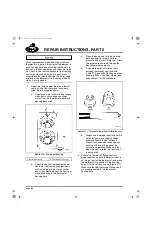
On vehicles so equipped, install the coupling
adapter(s) as follows before installing the cool
tube:
앫
Install a
new
wire-mesh gasket on the EGR
cool tube coupling adapter(s).
앫
Install the coupling adapter(s) to the EGR
cooler flange and/or the EGR mixer tube
flange using a band clamp. Tighten the band
clamp nut to 110 lb-in (12.4 N
폷
m).
On systems equipped with flange-style coupling
adapters on the EGR cool tube side of the
system, the flange clamps can be reused if there
is no damage and the threads are not corroded.
However, with damaged or corroded threads, the
clamps cannot be tightened to the proper torque
specification for a gas-tight seal. Replace the
T-bolt and nut or complete clamp assembly, if
corrosion or damage is present.
Install the one-piece cool tube assembly as
instructed below:
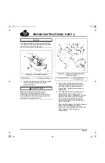
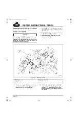
1. Slide a hose clamp onto the EGR mixer tube
and the EGR cooler cool-tube ports (or
coupling adapters, if so equipped).
2. Slide a hose clamp and the appropriate
coupling hose over each end of the EGR
cool tube assembly. The stepped-design
hose is used at the cooler connection.
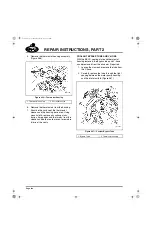
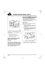
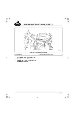
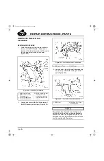
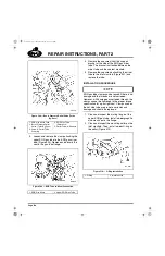
3. Place the cool tube assembly in position on
the engine between the EGR mixer tube and
cooler ports (or coupling adapters). Slide the
coupling hoses onto the ports/adapters and
secure with the hose clamps (Figure 490).
Place the cool tube in position under the
turbocharger oil supply and VTG actuator air lines
if the lines are already installed.
490
Figure 490 — Cool Tube Hose Connection (Cooler
Connection Shown)
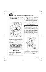
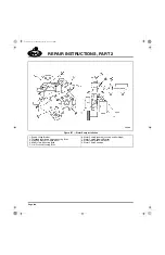
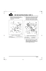
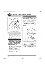
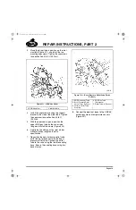
4. Install the clamps and mounting bolts to
secure the cool tube to the mounting
brackets at the EGR valve and the front
exhaust manifold (Figure 491). Tighten the
bolts to 96 lb-in (11 N
폷
m).
1. Hose Clamps
2. Coupling Hose
5-111.bk Page 406 Monday, July 10, 2006 2:26 PM
Содержание ASET AC
Страница 6: ...TABLE OF CONTENTS Page iii TABLE OF CONTENTS 5 111 bk Page iii Monday July 10 2006 2 26 PM...
Страница 14: ...INTRODUCTION Page 1 INTRODUCTION 5 111 bk Page 1 Monday July 10 2006 2 26 PM...
Страница 23: ...Page 10 NOTES 5 111 bk Page 10 Monday July 10 2006 2 26 PM...
Страница 24: ...VISUAL IDENTIFICATION Page 11 VISUAL IDENTIFICATION 5 111 bk Page 11 Monday July 10 2006 2 26 PM...
Страница 28: ...DESCRIPTION AND OPERATION Page 15 DESCRIPTION AND OPERATION 5 111 bk Page 15 Monday July 10 2006 2 26 PM...
Страница 96: ...COMPONENT LOCATOR Page 83 COMPONENT LOCATOR 5 111 bk Page 83 Monday July 10 2006 2 26 PM...
Страница 99: ...Page 86 NOTES 5 111 bk Page 86 Monday July 10 2006 2 26 PM...
Страница 100: ...TROUBLESHOOTING Page 87 TROUBLESHOOTING 5 111 bk Page 87 Monday July 10 2006 2 26 PM...
Страница 140: ...MAINTENANCE Page 127 MAINTENANCE 5 111 bk Page 127 Monday July 10 2006 2 26 PM...
Страница 153: ...Page 140 NOTES 5 111 bk Page 140 Monday July 10 2006 2 26 PM...
Страница 154: ...REPAIR INSTRUCTIONS PART 1 Page 141 REPAIR INSTRUCTIONS PART 1 5 111 bk Page 141 Monday July 10 2006 2 26 PM...
Страница 383: ...Page 370 NOTES 5 111 bk Page 370 Monday July 10 2006 2 26 PM...
Страница 384: ...REPAIR INSTRUCTIONS PART 2 Page 371 REPAIR INSTRUCTIONS PART 2 5 111 bk Page 371 Monday July 10 2006 2 26 PM...
Страница 454: ...REPAIR INSTRUCTIONS PART 3 Page 441 REPAIR INSTRUCTIONS PART 3 5 111 bk Page 441 Monday July 10 2006 2 26 PM...
Страница 479: ...Page 466 NOTES 5 111 bk Page 466 Monday July 10 2006 2 26 PM...
Страница 480: ...SPECIFICATIONS Page 467 SPECIFICATIONS 5 111 bk Page 467 Monday July 10 2006 2 26 PM...
Страница 505: ...Page 492 NOTES 5 111 bk Page 492 Monday July 10 2006 2 26 PM...
Страница 506: ...SCHEMATIC ROUTING DIAGRAMS Page 493 SCHEMATIC ROUTING DIAGRAMS 5 111 bk Page 493 Monday July 10 2006 2 26 PM...
Страница 513: ...Page 500 NOTES 5 111 bk Page 500 Monday July 10 2006 2 26 PM...
Страница 514: ...SPECIAL TOOLS EQUIPMENT Page 501 SPECIAL TOOLS EQUIPMENT 5 111 bk Page 501 Monday July 10 2006 2 26 PM...
Страница 519: ...Page 506 NOTES 5 111 bk Page 506 Monday July 10 2006 2 26 PM...
Страница 520: ...APPENDIX Page 507 APPENDIX 5 111 bk Page 507 Monday July 10 2006 2 26 PM...
Страница 528: ...INDEX Page 515 INDEX Index fm Page 515 Monday July 10 2006 2 48 PM...
Страница 535: ...Page 522 NOTES Index fm Page 522 Monday July 10 2006 2 48 PM...