Page 132
MAINTENANCE
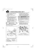
111
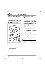
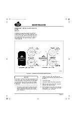
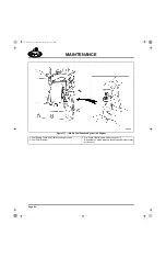
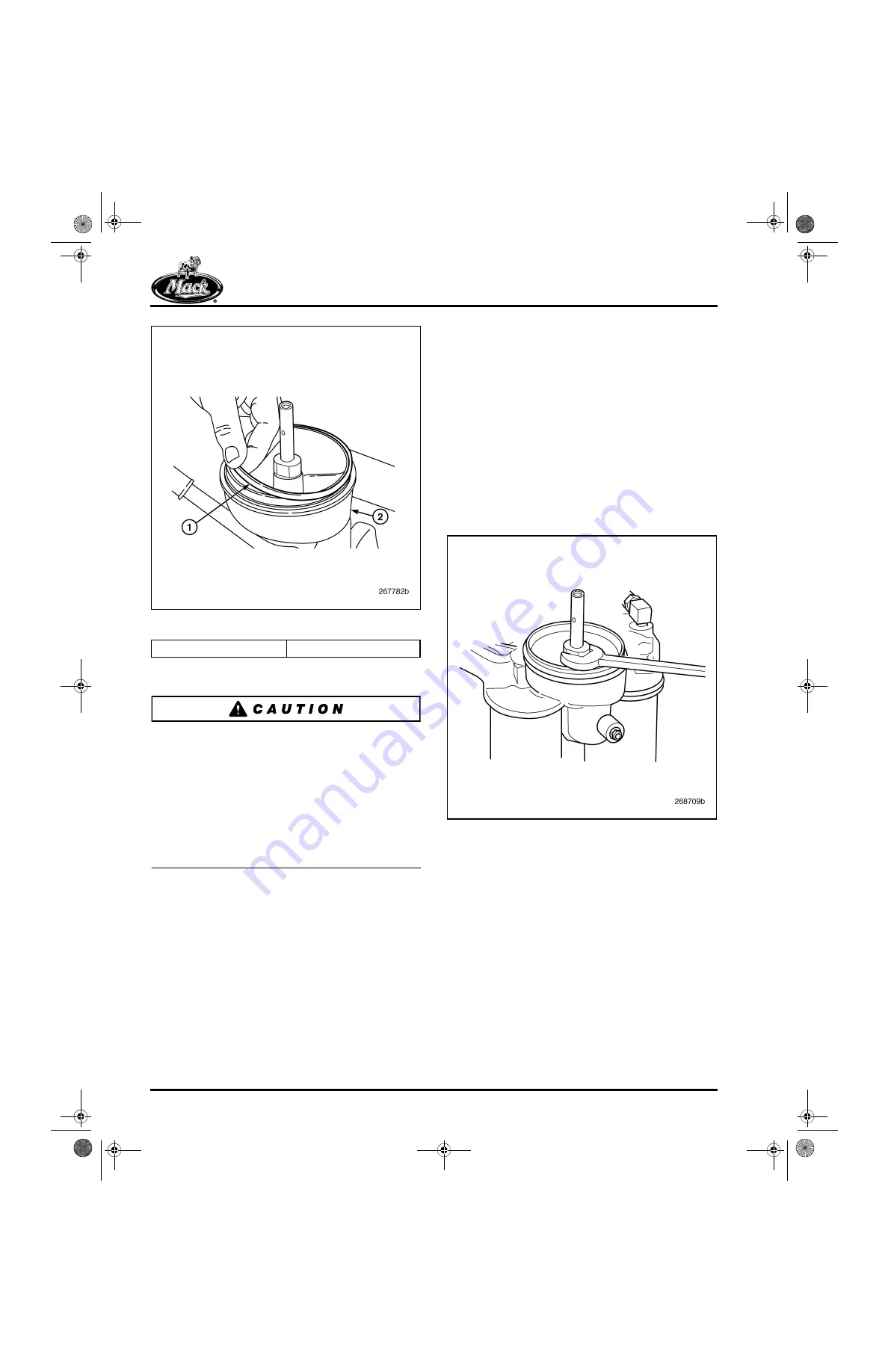
Figure 111 — O-Ring Installation
7. Install a
new
rotor over the spindle.
Use the correct rotor kit for the centrifugal filter
assembly application, 57GC2206 for Centri-Max
®
ULTRA and 57GC2231 for Centri-Max
®
ULTRA
PLUS. For easy identification, the ULTRA PLUS
rotor is black, whereas the ULTRA rotor is cream
color. If the ULTRA rotor is used in an ULTRA
PLUS application, the rotor bushings will be a
very loose fit on the smaller diameter shaft and
the rotor will not rotate, resulting in a
non-functioning centrifugal filter.
8. Install the cover assembly and tighten the
retaining nut to 19 lb-ft (26 N
폷
m).
9. Start the engine and check for leaks.
Centri-Max
®
ULTRA PLUS Spindle
Replacement (If Required)
The Centri-Max
®
ULTRA PLUS with the
two-piece spindle and new smaller diameter shaft
became the standard for all ASET™ engines in
the fourth quarter of 2003. This procedure covers
only this latest style filter arrangement.
1. Remove the cover assembly, rotor and
O-ring following the steps in the preceding
oil filter replacement procedure.
2. Using an open end wrench, remove the
lower shaft from the oil filter mounting
adapter.
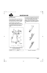
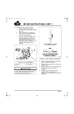
112
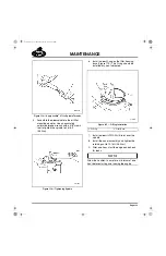
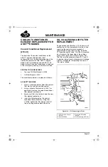
Figure 112 — Removing Lower Spindle from Oil Filter
Mounting Adapter
3. Clean the spindle mating threads in the oil
filter mounting adapter with Loctite
®
Non-Chlorinated Parts Cleaner (or similar
type of safety solvent) and blow the area dry
with clean shop air.
4. Apply Loctite
®
271 to the threads on the
lower end of the
new
spindle.
1. O-Ring
2. Filter Base
5-111.bk Page 132 Monday, July 10, 2006 2:26 PM
Содержание ASET AC
Страница 6: ...TABLE OF CONTENTS Page iii TABLE OF CONTENTS 5 111 bk Page iii Monday July 10 2006 2 26 PM...
Страница 14: ...INTRODUCTION Page 1 INTRODUCTION 5 111 bk Page 1 Monday July 10 2006 2 26 PM...
Страница 23: ...Page 10 NOTES 5 111 bk Page 10 Monday July 10 2006 2 26 PM...
Страница 24: ...VISUAL IDENTIFICATION Page 11 VISUAL IDENTIFICATION 5 111 bk Page 11 Monday July 10 2006 2 26 PM...
Страница 28: ...DESCRIPTION AND OPERATION Page 15 DESCRIPTION AND OPERATION 5 111 bk Page 15 Monday July 10 2006 2 26 PM...
Страница 96: ...COMPONENT LOCATOR Page 83 COMPONENT LOCATOR 5 111 bk Page 83 Monday July 10 2006 2 26 PM...
Страница 99: ...Page 86 NOTES 5 111 bk Page 86 Monday July 10 2006 2 26 PM...
Страница 100: ...TROUBLESHOOTING Page 87 TROUBLESHOOTING 5 111 bk Page 87 Monday July 10 2006 2 26 PM...
Страница 140: ...MAINTENANCE Page 127 MAINTENANCE 5 111 bk Page 127 Monday July 10 2006 2 26 PM...
Страница 153: ...Page 140 NOTES 5 111 bk Page 140 Monday July 10 2006 2 26 PM...
Страница 154: ...REPAIR INSTRUCTIONS PART 1 Page 141 REPAIR INSTRUCTIONS PART 1 5 111 bk Page 141 Monday July 10 2006 2 26 PM...
Страница 383: ...Page 370 NOTES 5 111 bk Page 370 Monday July 10 2006 2 26 PM...
Страница 384: ...REPAIR INSTRUCTIONS PART 2 Page 371 REPAIR INSTRUCTIONS PART 2 5 111 bk Page 371 Monday July 10 2006 2 26 PM...
Страница 454: ...REPAIR INSTRUCTIONS PART 3 Page 441 REPAIR INSTRUCTIONS PART 3 5 111 bk Page 441 Monday July 10 2006 2 26 PM...
Страница 479: ...Page 466 NOTES 5 111 bk Page 466 Monday July 10 2006 2 26 PM...
Страница 480: ...SPECIFICATIONS Page 467 SPECIFICATIONS 5 111 bk Page 467 Monday July 10 2006 2 26 PM...
Страница 505: ...Page 492 NOTES 5 111 bk Page 492 Monday July 10 2006 2 26 PM...
Страница 506: ...SCHEMATIC ROUTING DIAGRAMS Page 493 SCHEMATIC ROUTING DIAGRAMS 5 111 bk Page 493 Monday July 10 2006 2 26 PM...
Страница 513: ...Page 500 NOTES 5 111 bk Page 500 Monday July 10 2006 2 26 PM...
Страница 514: ...SPECIAL TOOLS EQUIPMENT Page 501 SPECIAL TOOLS EQUIPMENT 5 111 bk Page 501 Monday July 10 2006 2 26 PM...
Страница 519: ...Page 506 NOTES 5 111 bk Page 506 Monday July 10 2006 2 26 PM...
Страница 520: ...APPENDIX Page 507 APPENDIX 5 111 bk Page 507 Monday July 10 2006 2 26 PM...
Страница 528: ...INDEX Page 515 INDEX Index fm Page 515 Monday July 10 2006 2 48 PM...
Страница 535: ...Page 522 NOTES Index fm Page 522 Monday July 10 2006 2 48 PM...

