


Page 422
REPAIR INSTRUCTIONS, PART 2
VTG TURBOCHARGER
SERVICE PROCEDURES
ASET™ AC (CEGR) ENGINE
[214 SD]
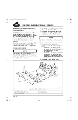
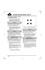
Preliminary Steps
The preliminary steps for replacing the VTG
turbocharger components will vary depending on
the chassis configuration. As such, the steps in
the procedures that follow are general in nature.
Begin the operations by disconnecting the
batteries and draining fluids from the engine as
required. Then, remove ducting and any
accessory items, etc., that may interfere with
access to the VTG turbocharger and related
components.
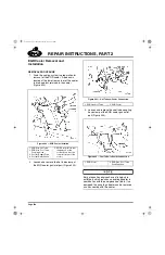
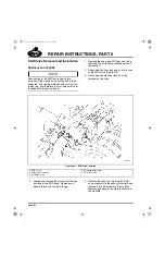
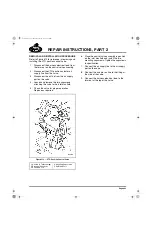
VTG Position Control Valve
Removal and Installation
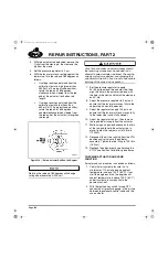
GENERAL INFORMATION
The electronically controlled VTG Position
Control Valve incorporates a bleed port that
exhausts air continually when the key is in the
“on” position and the engine is running. There is
no air flowing from the bleed port when the
engine is not running except under the following
conditions:
앫
When calibrating the VTG actuating system,
the control valve is operational and will bleed
air. This is normal.
앫
Statically, the VTG vanes should be fully
open. If there is a problem which has
resulted in the vanes not being fully open,
the VTG control valve may be operating and
trying to open the vanes. Under this
condition, the valve may bleed air. If this
occurs, the source of the problem must be
found and corrected.
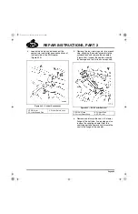
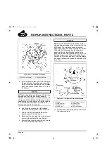
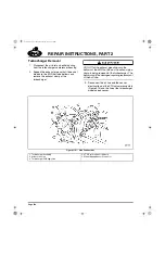
On early-production engines (prior to May 4,
2004), supply air enters the control valve directly
from the chassis air system. As a result, small
amounts of oil mist in the chassis air system can
condense inside the valve. It is a normal condition
to notice some oil seepage from the bleed port.
If the amount of oil is deemed excessive, the root
cause must be corrected. The VTG control valve
IS NOT the cause and should not be replaced
because of an excessive oil leak at the valve port.
The valve should only be replaced when it is not
functioning properly as identified by a fault code
and verified by troubleshooting procedures.
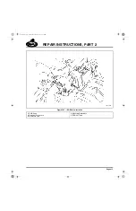
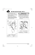
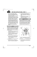
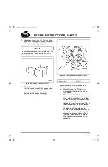
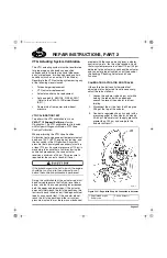
Engines produced after May 4, 2004 have an oil
coalescing air filter incorporated into the air line
supplying the control valve to prevent oil
condensation and possible “coking” inside the
VTG position control valve. The filter is mounted
on a bracket at the lower side of the cylinder
block, to the rear of the oil filters. A service parts
kit is available to retrofit early-production engines
if conditions warrant it.
5-111.bk Page 422 Monday, July 10, 2006 2:26 PM
Содержание ASET AC
Страница 6: ...TABLE OF CONTENTS Page iii TABLE OF CONTENTS 5 111 bk Page iii Monday July 10 2006 2 26 PM...
Страница 14: ...INTRODUCTION Page 1 INTRODUCTION 5 111 bk Page 1 Monday July 10 2006 2 26 PM...
Страница 23: ...Page 10 NOTES 5 111 bk Page 10 Monday July 10 2006 2 26 PM...
Страница 24: ...VISUAL IDENTIFICATION Page 11 VISUAL IDENTIFICATION 5 111 bk Page 11 Monday July 10 2006 2 26 PM...
Страница 28: ...DESCRIPTION AND OPERATION Page 15 DESCRIPTION AND OPERATION 5 111 bk Page 15 Monday July 10 2006 2 26 PM...
Страница 96: ...COMPONENT LOCATOR Page 83 COMPONENT LOCATOR 5 111 bk Page 83 Monday July 10 2006 2 26 PM...
Страница 99: ...Page 86 NOTES 5 111 bk Page 86 Monday July 10 2006 2 26 PM...
Страница 100: ...TROUBLESHOOTING Page 87 TROUBLESHOOTING 5 111 bk Page 87 Monday July 10 2006 2 26 PM...
Страница 140: ...MAINTENANCE Page 127 MAINTENANCE 5 111 bk Page 127 Monday July 10 2006 2 26 PM...
Страница 153: ...Page 140 NOTES 5 111 bk Page 140 Monday July 10 2006 2 26 PM...
Страница 154: ...REPAIR INSTRUCTIONS PART 1 Page 141 REPAIR INSTRUCTIONS PART 1 5 111 bk Page 141 Monday July 10 2006 2 26 PM...
Страница 383: ...Page 370 NOTES 5 111 bk Page 370 Monday July 10 2006 2 26 PM...
Страница 384: ...REPAIR INSTRUCTIONS PART 2 Page 371 REPAIR INSTRUCTIONS PART 2 5 111 bk Page 371 Monday July 10 2006 2 26 PM...
Страница 454: ...REPAIR INSTRUCTIONS PART 3 Page 441 REPAIR INSTRUCTIONS PART 3 5 111 bk Page 441 Monday July 10 2006 2 26 PM...
Страница 479: ...Page 466 NOTES 5 111 bk Page 466 Monday July 10 2006 2 26 PM...
Страница 480: ...SPECIFICATIONS Page 467 SPECIFICATIONS 5 111 bk Page 467 Monday July 10 2006 2 26 PM...
Страница 505: ...Page 492 NOTES 5 111 bk Page 492 Monday July 10 2006 2 26 PM...
Страница 506: ...SCHEMATIC ROUTING DIAGRAMS Page 493 SCHEMATIC ROUTING DIAGRAMS 5 111 bk Page 493 Monday July 10 2006 2 26 PM...
Страница 513: ...Page 500 NOTES 5 111 bk Page 500 Monday July 10 2006 2 26 PM...
Страница 514: ...SPECIAL TOOLS EQUIPMENT Page 501 SPECIAL TOOLS EQUIPMENT 5 111 bk Page 501 Monday July 10 2006 2 26 PM...
Страница 519: ...Page 506 NOTES 5 111 bk Page 506 Monday July 10 2006 2 26 PM...
Страница 520: ...APPENDIX Page 507 APPENDIX 5 111 bk Page 507 Monday July 10 2006 2 26 PM...
Страница 528: ...INDEX Page 515 INDEX Index fm Page 515 Monday July 10 2006 2 48 PM...
Страница 535: ...Page 522 NOTES Index fm Page 522 Monday July 10 2006 2 48 PM...