Page 40
DESCRIPTION AND OPERATION
Ambient Air Temperature Sensor
— P/N
64MT2118
The sensor is mounted off-engine and supplies
temperature input to the engine electronic control
unit (EECU). Location of the sensor depends
upon chassis model. But in general, it is located
at the front of the chassis mounted either on the
front crossmember behind the bumper, on a hood
hinge, hood hinge bracket, body, spring bracket
or grille guard assembly.
Combustion Air Temperature/Humidity
Sensor
— P/N 64MT445, mounted in the air inlet
tubing between the air cleaner and the
turbocharger.
VTG Position Sensor (New)
— P/N 64MT458,
mounted on top of the turbocharger VTG
actuator. It indicates the position of the vanes in
the turbine housing inlet port.
VTG Wheel-Speed Sensor (New)
— P/N
64MT457, mounted in the turbocharger bearing
housing where it is used to indicate turbocharger
wheel speed.
Compressor Discharge Temperature Sensor
(New)
— P/N 64MT450A, a wide-range
fast-response type mounted in the charged-air
tubing between the turbocharger and the
CMCAC.
Boost Pressure Sensor (New)
— P/N
64MT446, mounted in the EGR mixer tube.
CMCAC Outlet Temperature Sensor (New)
—
P/N 64MT450A, mounted in the EGR mixer tube.
EGR Temperature and MASS Flow Sensors
(New)
— Sensor pair mounted in the upper
“cool-side” EGR tube between the EGR cooler
and the mixer tube. The pair of sensors is
calibrated specifically to the upper EGR tube and
the EGR MASS Flow System module. If
replacement is required, the entire tube assembly
with its integral sensors must be replaced along
with the MASS Flow System module attached to
the back of the EECU cooling plate. Part numbers
for the tube assembly are 206MS52 (with
J-Tech™ engine brake) or P/N 206MS51 (without
engine brake).
Atmospheric Pressure Sensor
— Integral to the
EECU module.
Inlet Manifold Temperature Sensor
— P/N
64MT450A, mounted at a mid-point on the inlet
manifold.
Oil Pressure Sensor
— Mounted at the side of
the oil filter adapter housing.
Oil Temperature Sensor
— Mounted at the side
of the oil filter adapter housing.
Coolant Temperature Sensor
— Mounted at the
rear of the coolant manifold.
Engine Speed Sensor
— Mounted at the left
side of the flywheel housing.
Engine Position Sensor
— Mounted on the front
timing cover beneath the crankcase breather
housing.
Fan Speed Sensor
— Mounted on the fan-drive
hub support.
Fuel Temperature Sensor
— V-MAC III
monitors fuel temperature at the cylinder block
fuel gallery inlet. This fuel temperature data is
used by the system to adjust fuel delivery for
optimized power and to provide accurate mpg
fuel consumption information.
All of these sensors are connected via a
reconfigured engine wiring harness. The harness
incorporates three geared lock-down connectors
at the EECU. The harness is also fitted with a
new Deutsch vehicle interface connector located
on the air inlet manifold below the VTG
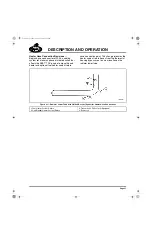
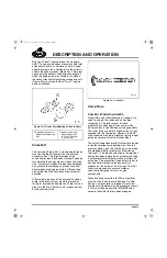
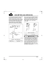
turbocharger position controller (Figure 36). This
connector provides the connection for the
interface between the engine control system and
the chassis.
36
Figure 36 — Deutsch Connector
1. Inlet Manifold
2. VTG Position Controller
3. Vehicle Interface
Connector
5-111.bk Page 40 Monday, July 10, 2006 2:26 PM
Содержание ASET AC
Страница 6: ...TABLE OF CONTENTS Page iii TABLE OF CONTENTS 5 111 bk Page iii Monday July 10 2006 2 26 PM...
Страница 14: ...INTRODUCTION Page 1 INTRODUCTION 5 111 bk Page 1 Monday July 10 2006 2 26 PM...
Страница 23: ...Page 10 NOTES 5 111 bk Page 10 Monday July 10 2006 2 26 PM...
Страница 24: ...VISUAL IDENTIFICATION Page 11 VISUAL IDENTIFICATION 5 111 bk Page 11 Monday July 10 2006 2 26 PM...
Страница 28: ...DESCRIPTION AND OPERATION Page 15 DESCRIPTION AND OPERATION 5 111 bk Page 15 Monday July 10 2006 2 26 PM...
Страница 96: ...COMPONENT LOCATOR Page 83 COMPONENT LOCATOR 5 111 bk Page 83 Monday July 10 2006 2 26 PM...
Страница 99: ...Page 86 NOTES 5 111 bk Page 86 Monday July 10 2006 2 26 PM...
Страница 100: ...TROUBLESHOOTING Page 87 TROUBLESHOOTING 5 111 bk Page 87 Monday July 10 2006 2 26 PM...
Страница 140: ...MAINTENANCE Page 127 MAINTENANCE 5 111 bk Page 127 Monday July 10 2006 2 26 PM...
Страница 153: ...Page 140 NOTES 5 111 bk Page 140 Monday July 10 2006 2 26 PM...
Страница 154: ...REPAIR INSTRUCTIONS PART 1 Page 141 REPAIR INSTRUCTIONS PART 1 5 111 bk Page 141 Monday July 10 2006 2 26 PM...
Страница 383: ...Page 370 NOTES 5 111 bk Page 370 Monday July 10 2006 2 26 PM...
Страница 384: ...REPAIR INSTRUCTIONS PART 2 Page 371 REPAIR INSTRUCTIONS PART 2 5 111 bk Page 371 Monday July 10 2006 2 26 PM...
Страница 454: ...REPAIR INSTRUCTIONS PART 3 Page 441 REPAIR INSTRUCTIONS PART 3 5 111 bk Page 441 Monday July 10 2006 2 26 PM...
Страница 479: ...Page 466 NOTES 5 111 bk Page 466 Monday July 10 2006 2 26 PM...
Страница 480: ...SPECIFICATIONS Page 467 SPECIFICATIONS 5 111 bk Page 467 Monday July 10 2006 2 26 PM...
Страница 505: ...Page 492 NOTES 5 111 bk Page 492 Monday July 10 2006 2 26 PM...
Страница 506: ...SCHEMATIC ROUTING DIAGRAMS Page 493 SCHEMATIC ROUTING DIAGRAMS 5 111 bk Page 493 Monday July 10 2006 2 26 PM...
Страница 513: ...Page 500 NOTES 5 111 bk Page 500 Monday July 10 2006 2 26 PM...
Страница 514: ...SPECIAL TOOLS EQUIPMENT Page 501 SPECIAL TOOLS EQUIPMENT 5 111 bk Page 501 Monday July 10 2006 2 26 PM...
Страница 519: ...Page 506 NOTES 5 111 bk Page 506 Monday July 10 2006 2 26 PM...
Страница 520: ...APPENDIX Page 507 APPENDIX 5 111 bk Page 507 Monday July 10 2006 2 26 PM...
Страница 528: ...INDEX Page 515 INDEX Index fm Page 515 Monday July 10 2006 2 48 PM...
Страница 535: ...Page 522 NOTES Index fm Page 522 Monday July 10 2006 2 48 PM...

