REPAIR INSTRUCTIONS, PART 2
Page 385
H-Ring Dislodgement Inspection
Dislodging of the H-ring from its bore results from
valve lifter inertia forcing the H-ring upward.
When the H-ring at a failure cylinder is higher
than that of an adjacent cylinder, the appropriate
action must be taken depending upon how much
the H-ring has been pushed upward. Measure the
installation depth of the H-ring as follows:
1. If not previously done, remove the push rod
and look down the push rod hole, observing
the top of the lifter and the top of the H-ring.
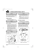
2. Place a length of welding rod (approximately
15 inches long) on top of the H-ring, at the
outboard side. Refer to Figure 457.
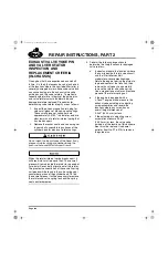
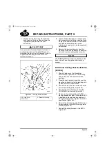
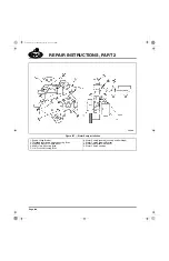
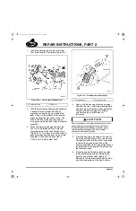
457
Figure 457 — H-Ring Measuring Point
3. Place a straightedge on the cylinder head
top rail surface, in contact with the welding
rod.
4. Mark the welding rod at the point where it
contacts the straightedge.
5. Perform the same check at an adjacent
cylinder and mark its point of contact on the
welding rod. Compare the measurement
taken at the adjacent cylinder with the
measurement taken at the suspect failure
cylinder.
앫
If the H-ring at the failure cylinder is the
same height-to-1/16 inch (0–1.587 mm)
higher as compared to that of an
adjacent OK cylinder, it is concluded
that no partial dislodging of the H-ring
has occurred. No further action is
required.
앫
If the H-ring at the failure cylinder is
1/16–1/8 inch (1.587–3.175 mm) higher
than that of an adjacent OK cylinder,
the H-ring position is OK.
앫
If the H-ring is more than 1/8 inch
(3.175 mm) higher than that of an
adjacent OK cylinder, the H-ring has
become dislodged and must be
replaced.
H-Ring Alignment Inspection
H-ring alignment is checked with H-ring alignment
checking tool No. J 46083 as follows:
1. With the camshaft and lifters removed, insert
the alignment checking tool J 46083 into the
mating pair of lifter bores from the crankcase
side.
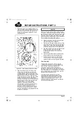
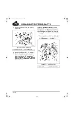
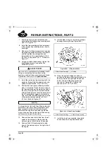
458
Figure 458 — Alignment Tool Inserted into Lifter Bore
2. Check to see if the depth groove on the tool
handle aligns with the oil pan mounting
surface of the cylinder block. If both H-rings
are in alignment, the tool will be inserted all
the way into the lifter bores, and the depth
groove on the handle will align with the oil
pan mounting surface. If either of the H-rings
is not in alignment, the tool will not fully
insert into the lifter bores and the insertion
depth groove on the tool handle will not align
with the oil pan mounting surface.
5-111.bk Page 385 Monday, July 10, 2006 2:26 PM
Содержание ASET AC
Страница 6: ...TABLE OF CONTENTS Page iii TABLE OF CONTENTS 5 111 bk Page iii Monday July 10 2006 2 26 PM...
Страница 14: ...INTRODUCTION Page 1 INTRODUCTION 5 111 bk Page 1 Monday July 10 2006 2 26 PM...
Страница 23: ...Page 10 NOTES 5 111 bk Page 10 Monday July 10 2006 2 26 PM...
Страница 24: ...VISUAL IDENTIFICATION Page 11 VISUAL IDENTIFICATION 5 111 bk Page 11 Monday July 10 2006 2 26 PM...
Страница 28: ...DESCRIPTION AND OPERATION Page 15 DESCRIPTION AND OPERATION 5 111 bk Page 15 Monday July 10 2006 2 26 PM...
Страница 96: ...COMPONENT LOCATOR Page 83 COMPONENT LOCATOR 5 111 bk Page 83 Monday July 10 2006 2 26 PM...
Страница 99: ...Page 86 NOTES 5 111 bk Page 86 Monday July 10 2006 2 26 PM...
Страница 100: ...TROUBLESHOOTING Page 87 TROUBLESHOOTING 5 111 bk Page 87 Monday July 10 2006 2 26 PM...
Страница 140: ...MAINTENANCE Page 127 MAINTENANCE 5 111 bk Page 127 Monday July 10 2006 2 26 PM...
Страница 153: ...Page 140 NOTES 5 111 bk Page 140 Monday July 10 2006 2 26 PM...
Страница 154: ...REPAIR INSTRUCTIONS PART 1 Page 141 REPAIR INSTRUCTIONS PART 1 5 111 bk Page 141 Monday July 10 2006 2 26 PM...
Страница 383: ...Page 370 NOTES 5 111 bk Page 370 Monday July 10 2006 2 26 PM...
Страница 384: ...REPAIR INSTRUCTIONS PART 2 Page 371 REPAIR INSTRUCTIONS PART 2 5 111 bk Page 371 Monday July 10 2006 2 26 PM...
Страница 454: ...REPAIR INSTRUCTIONS PART 3 Page 441 REPAIR INSTRUCTIONS PART 3 5 111 bk Page 441 Monday July 10 2006 2 26 PM...
Страница 479: ...Page 466 NOTES 5 111 bk Page 466 Monday July 10 2006 2 26 PM...
Страница 480: ...SPECIFICATIONS Page 467 SPECIFICATIONS 5 111 bk Page 467 Monday July 10 2006 2 26 PM...
Страница 505: ...Page 492 NOTES 5 111 bk Page 492 Monday July 10 2006 2 26 PM...
Страница 506: ...SCHEMATIC ROUTING DIAGRAMS Page 493 SCHEMATIC ROUTING DIAGRAMS 5 111 bk Page 493 Monday July 10 2006 2 26 PM...
Страница 513: ...Page 500 NOTES 5 111 bk Page 500 Monday July 10 2006 2 26 PM...
Страница 514: ...SPECIAL TOOLS EQUIPMENT Page 501 SPECIAL TOOLS EQUIPMENT 5 111 bk Page 501 Monday July 10 2006 2 26 PM...
Страница 519: ...Page 506 NOTES 5 111 bk Page 506 Monday July 10 2006 2 26 PM...
Страница 520: ...APPENDIX Page 507 APPENDIX 5 111 bk Page 507 Monday July 10 2006 2 26 PM...
Страница 528: ...INDEX Page 515 INDEX Index fm Page 515 Monday July 10 2006 2 48 PM...
Страница 535: ...Page 522 NOTES Index fm Page 522 Monday July 10 2006 2 48 PM...

