REPAIR INSTRUCTIONS, PART 2
Page 427
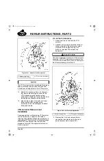
7. If the V-band is loosened for angular
orientation of the compressor housing,
ensure that the mating flanges are tightly
seated and that the V-band is snug but will
still allow cover orientation.
Complete the orientation of the cover and
housing before making any rigid connections
to the compressor inlet. Tighten the V-band
retaining nut to 105 lb-in (12 N
폷
m), using
torque wrench J 5853-C, or equivalent.
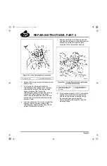
Make certain that all ducting aligns closely
with the turbocharger. This minimizes
external stresses acting on the unit. Then,
taking care to not pinch the wires in the wire
routing clamp, tighten the clamp retaining
nut on the V-band bolt to 48 lb-in (5 N
폷
m).
Make sure the wire clamp remains vertical
when tightening the nut, to keep the wires
away from the hot surfaces of the
compressor cover, bearing and turbine
housings.
Replacement VTG turbochargers have not been
given the final orientation of the housings and the
fasteners that allow orientation are not tightened
to specification. When installing a replacement
turbocharger, orient the housings and tighten the
fasteners as follows:
앫
Tighten the compressor housing clamp band
retaining nut and wire routing clamp nut as
described in the above step.
앫
Tighten the six screws that secure the three
clamp plates and bearing housing to the
turbine housing. Tighten the screws to
30 lb-ft (41 N
폷
m).
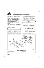
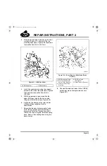
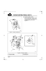
8. Install the oil drain tube (Figure 515) and
tighten the capscrews to the specification,
15 lb-ft (20 N
폷
m), using torque wrench
J 24406, or equivalent.
9. Connect the EGR valve oil return line to the
oil drain tube.
10. Remove and flush the turbocharger oil
supply line to make sure it is clean and free
of debris. Then, reinstall the supply line.
11. Install and adjust the VTG actuator (if
removed) using the procedure under “VTG
Removal and Installation” included in this
section.
12. Route and tie the VTG air line to the oil lines
supplying the EGR valve and the
turbocharger. Use stainless steel tie straps
to secure the lines together.
Proper routing will hold the air line in a position
maximizing its distance away from and avoiding
contact with the EGR valve casting and the upper
EGR cool tube bellows. If this is not done, heat
from the EGR valve can damage the Teflon
®
core of the line causing an air leak. In addition,
the outer braid of the air line can chafe the cool
tube bellows and cause an exhaust leak.
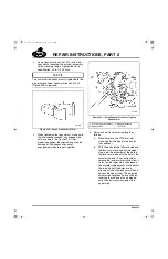
518
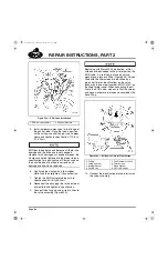
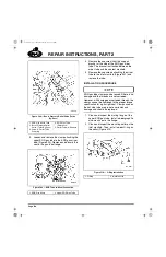
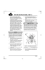
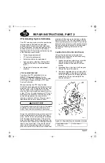
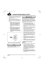
Figure 518 — Vane Operating Lever Connection
13. Connect the actuator air line and the VTG
position sensor electrical lead to complete
the procedure.
1. Actuator Rod
2. Vane Operating Lever
5-111.bk Page 427 Monday, July 10, 2006 2:26 PM
Содержание ASET AC
Страница 6: ...TABLE OF CONTENTS Page iii TABLE OF CONTENTS 5 111 bk Page iii Monday July 10 2006 2 26 PM...
Страница 14: ...INTRODUCTION Page 1 INTRODUCTION 5 111 bk Page 1 Monday July 10 2006 2 26 PM...
Страница 23: ...Page 10 NOTES 5 111 bk Page 10 Monday July 10 2006 2 26 PM...
Страница 24: ...VISUAL IDENTIFICATION Page 11 VISUAL IDENTIFICATION 5 111 bk Page 11 Monday July 10 2006 2 26 PM...
Страница 28: ...DESCRIPTION AND OPERATION Page 15 DESCRIPTION AND OPERATION 5 111 bk Page 15 Monday July 10 2006 2 26 PM...
Страница 96: ...COMPONENT LOCATOR Page 83 COMPONENT LOCATOR 5 111 bk Page 83 Monday July 10 2006 2 26 PM...
Страница 99: ...Page 86 NOTES 5 111 bk Page 86 Monday July 10 2006 2 26 PM...
Страница 100: ...TROUBLESHOOTING Page 87 TROUBLESHOOTING 5 111 bk Page 87 Monday July 10 2006 2 26 PM...
Страница 140: ...MAINTENANCE Page 127 MAINTENANCE 5 111 bk Page 127 Monday July 10 2006 2 26 PM...
Страница 153: ...Page 140 NOTES 5 111 bk Page 140 Monday July 10 2006 2 26 PM...
Страница 154: ...REPAIR INSTRUCTIONS PART 1 Page 141 REPAIR INSTRUCTIONS PART 1 5 111 bk Page 141 Monday July 10 2006 2 26 PM...
Страница 383: ...Page 370 NOTES 5 111 bk Page 370 Monday July 10 2006 2 26 PM...
Страница 384: ...REPAIR INSTRUCTIONS PART 2 Page 371 REPAIR INSTRUCTIONS PART 2 5 111 bk Page 371 Monday July 10 2006 2 26 PM...
Страница 454: ...REPAIR INSTRUCTIONS PART 3 Page 441 REPAIR INSTRUCTIONS PART 3 5 111 bk Page 441 Monday July 10 2006 2 26 PM...
Страница 479: ...Page 466 NOTES 5 111 bk Page 466 Monday July 10 2006 2 26 PM...
Страница 480: ...SPECIFICATIONS Page 467 SPECIFICATIONS 5 111 bk Page 467 Monday July 10 2006 2 26 PM...
Страница 505: ...Page 492 NOTES 5 111 bk Page 492 Monday July 10 2006 2 26 PM...
Страница 506: ...SCHEMATIC ROUTING DIAGRAMS Page 493 SCHEMATIC ROUTING DIAGRAMS 5 111 bk Page 493 Monday July 10 2006 2 26 PM...
Страница 513: ...Page 500 NOTES 5 111 bk Page 500 Monday July 10 2006 2 26 PM...
Страница 514: ...SPECIAL TOOLS EQUIPMENT Page 501 SPECIAL TOOLS EQUIPMENT 5 111 bk Page 501 Monday July 10 2006 2 26 PM...
Страница 519: ...Page 506 NOTES 5 111 bk Page 506 Monday July 10 2006 2 26 PM...
Страница 520: ...APPENDIX Page 507 APPENDIX 5 111 bk Page 507 Monday July 10 2006 2 26 PM...
Страница 528: ...INDEX Page 515 INDEX Index fm Page 515 Monday July 10 2006 2 48 PM...
Страница 535: ...Page 522 NOTES Index fm Page 522 Monday July 10 2006 2 48 PM...


