System board switches
System board switches
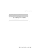
The following table provides the system switch identifiers and
descriptions of these switches. The system switch block is identified
by key
.13/
in the illustration at “Identifying parts on the system
board” on page 82.
Note: Turn off the server and disconnect the power cord before
moving any switches.
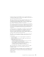
Table 2 (Page 1 of 2). System Board Switch Block
Identifier
Switch Description
1
Reserved
2
Reserved
3
Reserved
4
Reserved
5
BIOS recovery mode. When this switch is set to On, perform
BIOS recovery using the boot block (boot block recovery).
The recovery boot block is in a protected area of flash memory
that cannot be overwritten. When the BIOS becomes corrupted
(for example, if a power failure occurs during a flash update), the
recovery boot block can be used to restore the BIOS. The code in
the recovery boot block enables the server to start up and read a
flash diskette. The flash utility automatically recovers the system
BIOS from the BIOS recovery files on the diskette. When the
flash is complete, the switch must be moved to the Off position.
The default setting is Off (disabled).
6
Ethernet operation mode. When this switch is set to On, the
onboard Ethernet controller is disabled. When this switch is set
to Off, the onboard Ethernet controller operates normally.
The default setting is Off.
7
Administrator password locked. When this switch is set to On,
the administrator password is unlocked, and may be changed or
reset although enhanced security is enabled. When this switch is
set to Off, the administrator password is locked, and may not be
changed or reset if enhanced security is enabled.
The default setting is Off.
216
Netfinity 3500 M10 User's Handbook
Содержание Netfinity 3500 M10
Страница 1: ...Netfinity 3500 M10 User s Handbook...
Страница 2: ......
Страница 3: ...Netfinity 3500 M10 User s Handbook IBM...
Страница 14: ...xii Netfinity 3500 M10 User s Handbook...
Страница 18: ...xvi Netfinity 3500 M10 User s Handbook...
Страница 80: ...62 Netfinity 3500 M10 User s Handbook...
Страница 86: ...Interrupt and DMA resources 144 Interrupt resources 144 DMA resources 146 68 Netfinity 3500 M10 User s Handbook...
Страница 145: ...1 Use a tool such as a screwdriver to remove the two metal knockouts Metal Knockouts Chapter 5 Installing options 127...
Страница 228: ...210 Netfinity 3500 M10 User s Handbook...
Страница 236: ...System board switches 218 Netfinity 3500 M10 User s Handbook...
Страница 256: ...238 Netfinity 3500 M10 User s Handbook...
Страница 267: ......
Страница 268: ...IBM Part Number 37L6687 Printed in U S A July 1999 37L6687...

