Replacing the cover and connecting the cables
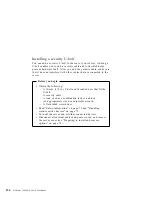
Before you begin
Read “Safety information” on page 70 and “Handling
static-sensitive devices” on page 72.
1. Ensure that all components have been reassembled correctly and
that no tools or loose screws are left inside your server.
2. Clear any cables that might impede the replacement of the
cover.
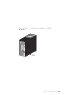
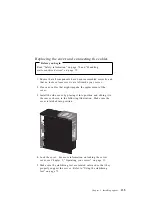
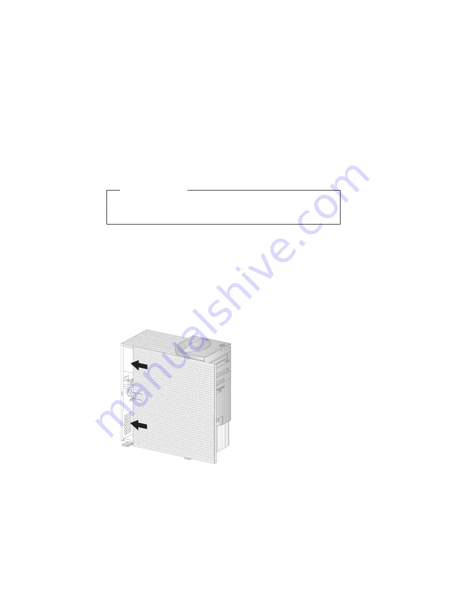
3. Install the side cover by placing it into position and sliding it to
the rear as shown in the following illustration. Make sure the
cover is latched into position.
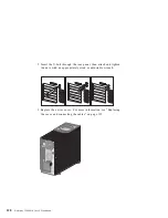
4. Lock the cover. For more information on locking the server
cover, see Chapter 2, “Operating your server” on page 11.
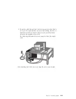
5. Make sure the stabilizing feet are rotated outward so that they
properly support the server. Refer to “Using the stabilizing
feet” on page 75.
Chapter 5. Installing options
135
Содержание Netfinity 3500 M10
Страница 1: ...Netfinity 3500 M10 User s Handbook...
Страница 2: ......
Страница 3: ...Netfinity 3500 M10 User s Handbook IBM...
Страница 14: ...xii Netfinity 3500 M10 User s Handbook...
Страница 18: ...xvi Netfinity 3500 M10 User s Handbook...
Страница 80: ...62 Netfinity 3500 M10 User s Handbook...
Страница 86: ...Interrupt and DMA resources 144 Interrupt resources 144 DMA resources 146 68 Netfinity 3500 M10 User s Handbook...
Страница 145: ...1 Use a tool such as a screwdriver to remove the two metal knockouts Metal Knockouts Chapter 5 Installing options 127...
Страница 228: ...210 Netfinity 3500 M10 User s Handbook...
Страница 236: ...System board switches 218 Netfinity 3500 M10 User s Handbook...
Страница 256: ...238 Netfinity 3500 M10 User s Handbook...
Страница 267: ......
Страница 268: ...IBM Part Number 37L6687 Printed in U S A July 1999 37L6687...

