Memory configuration
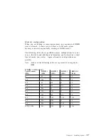
When you are adding or removing memory, any sequence of DIMM
sizes is allowed. A basic rule to follow is to fill each system
memory connector sequentially, starting at DIMM socket 1.
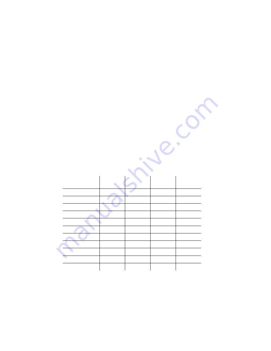
The following table shows possible memory configurations for your
server; this table and additional information can be found on a label
located inside your server. Again, alternative configurations are
possible.
Note: Values in the following table are represented in megabytes
(MB).
DIMM combinations
Total Memory
(MB)
DIMM 1
(MB)
DIMM 2
(MB)
DIMM 3
(MB)
DIMM 4
(MB)
64
64
0
0
0
128
128
0
0
0
128
64
64
0
0
192
64
64
64
0
256
256
0
0
0
256
128
128
0
0
256
128
64
64
0
512
128
128
128
128
512
256
256
0
0
768
256
256
256
0
1024 (1 GB)
256
256
256
256
Chapter 5. Installing options
87
Содержание Netfinity 3500 M10
Страница 1: ...Netfinity 3500 M10 User s Handbook...
Страница 2: ......
Страница 3: ...Netfinity 3500 M10 User s Handbook IBM...
Страница 14: ...xii Netfinity 3500 M10 User s Handbook...
Страница 18: ...xvi Netfinity 3500 M10 User s Handbook...
Страница 80: ...62 Netfinity 3500 M10 User s Handbook...
Страница 86: ...Interrupt and DMA resources 144 Interrupt resources 144 DMA resources 146 68 Netfinity 3500 M10 User s Handbook...
Страница 145: ...1 Use a tool such as a screwdriver to remove the two metal knockouts Metal Knockouts Chapter 5 Installing options 127...
Страница 228: ...210 Netfinity 3500 M10 User s Handbook...
Страница 236: ...System board switches 218 Netfinity 3500 M10 User s Handbook...
Страница 256: ...238 Netfinity 3500 M10 User s Handbook...
Страница 267: ......
Страница 268: ...IBM Part Number 37L6687 Printed in U S A July 1999 37L6687...

