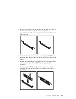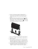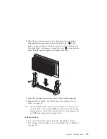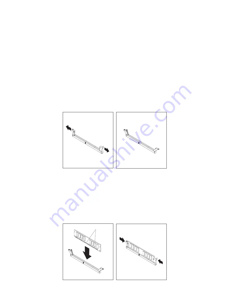
3. Be sure the retaining clips are in the open position, as shown in
the illustration on the right. If the retaining clips are
perpendicular with the connector, push outward on them until
they click open.
4. Touch the static-protective package containing the DIMM to any
unpainted (bare) metal surface in the server, and then remove the
DIMM.
5. Position the DIMM above the connector so that the two notches
on the bottom edge of the DIMM align properly with the
connector.
6. Firmly push the DIMM straight into the connector until the
retaining clips pop closed and snugly fit around both ends of
the DIMM.
Notches
Chapter 5. Installing options
89
Содержание Netfinity 3500 M10
Страница 1: ...Netfinity 3500 M10 User s Handbook...
Страница 2: ......
Страница 3: ...Netfinity 3500 M10 User s Handbook IBM...
Страница 14: ...xii Netfinity 3500 M10 User s Handbook...
Страница 18: ...xvi Netfinity 3500 M10 User s Handbook...
Страница 80: ...62 Netfinity 3500 M10 User s Handbook...
Страница 86: ...Interrupt and DMA resources 144 Interrupt resources 144 DMA resources 146 68 Netfinity 3500 M10 User s Handbook...
Страница 145: ...1 Use a tool such as a screwdriver to remove the two metal knockouts Metal Knockouts Chapter 5 Installing options 127...
Страница 228: ...210 Netfinity 3500 M10 User s Handbook...
Страница 236: ...System board switches 218 Netfinity 3500 M10 User s Handbook...
Страница 256: ...238 Netfinity 3500 M10 User s Handbook...
Страница 267: ......
Страница 268: ...IBM Part Number 37L6687 Printed in U S A July 1999 37L6687...

