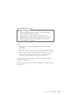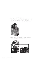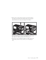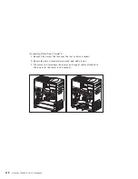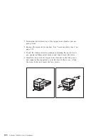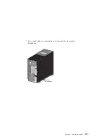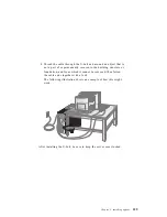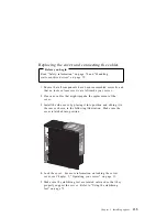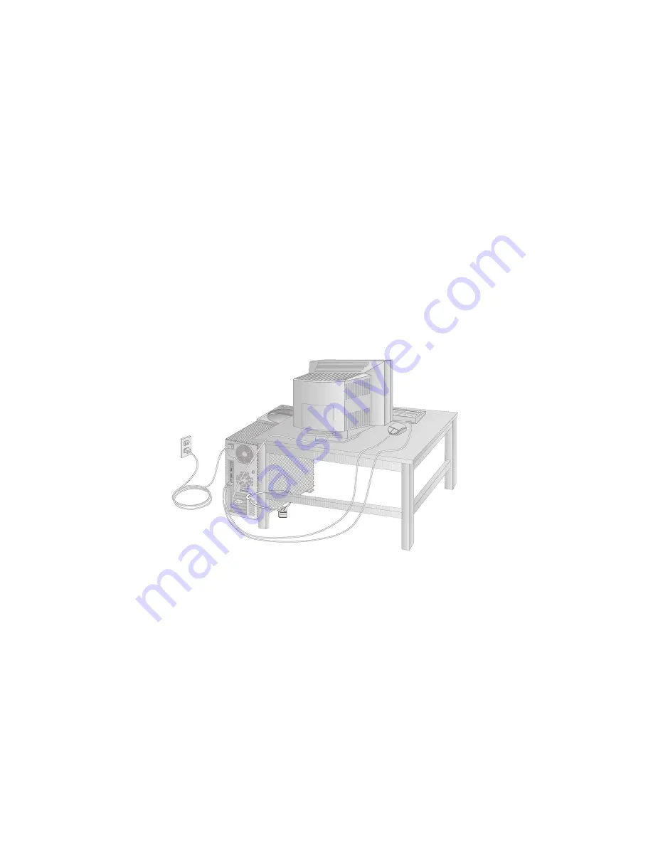
4. Thread the cable through the U-bolt and around an object that is
not a part of or permanently secured to the building structure or
foundation, and from which it cannot be removed; then fasten
the cable ends together with a lock.
The following illustration shows an example of how this might
work.
After installing the U-bolt, be sure to keep the server cover locked.
Chapter 5. Installing options
129
Содержание Netfinity 3500 M10
Страница 1: ...Netfinity 3500 M10 User s Handbook...
Страница 2: ......
Страница 3: ...Netfinity 3500 M10 User s Handbook IBM...
Страница 14: ...xii Netfinity 3500 M10 User s Handbook...
Страница 18: ...xvi Netfinity 3500 M10 User s Handbook...
Страница 80: ...62 Netfinity 3500 M10 User s Handbook...
Страница 86: ...Interrupt and DMA resources 144 Interrupt resources 144 DMA resources 146 68 Netfinity 3500 M10 User s Handbook...
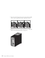
Страница 145: ...1 Use a tool such as a screwdriver to remove the two metal knockouts Metal Knockouts Chapter 5 Installing options 127...
Страница 228: ...210 Netfinity 3500 M10 User s Handbook...
Страница 236: ...System board switches 218 Netfinity 3500 M10 User s Handbook...
Страница 256: ...238 Netfinity 3500 M10 User s Handbook...
Страница 267: ......
Страница 268: ...IBM Part Number 37L6687 Printed in U S A July 1999 37L6687...

