- 52 -
Analog Mode
In the Analog Torque or Velocity mode, the servo amplifier responds to a conventional
±
10 volt
DC signal. Most variable speed drives and servo amplifiers on the market today receive
commands via this type of signal. If the DIP switches are set to enable this mode, the display
character of the digital drive will be an (A). In this mode, a
±
10 volt command signal is equated
to
±
velocity or peak torque as determined by the drives preprogrammed velocity (3000 RPM
default) or peak torque based on drive size.
±
10 =
±
peak torque. The external and serial control
modes are not ignored if an (A) is on the display. Sending an SC=1 to the drive would disable
analog control and enable serial control with an (E) being on the display. If an (A) was on the
display and an initiate index home or job from the I/O occurs, then the (A) will be replaced with
an (E) and the requested motion occurs. At the end of motion, the display and mode revert to
(A).
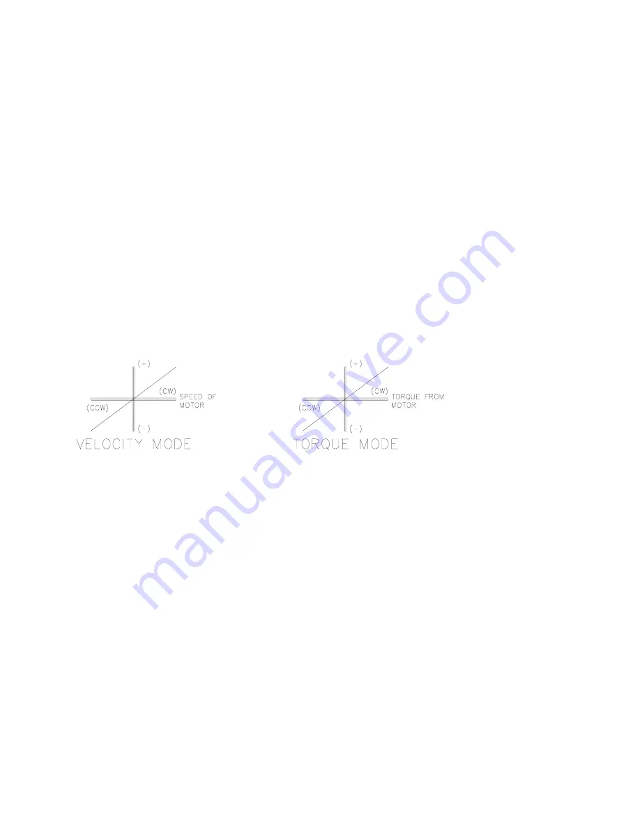
In either of the two analog modes of operation a (+)/(-) 10 VDC signal is equated to either (CW)
or (CCW) maximum programmed velocity in the velocity mode or CW or CCW full peak rating
in the torque mode. The mode of operation can be selected via the mode select switches on the
front of the servo drive.
NOTE: CW rotation is defined while facing the shaft end of the motor.
Figure 42
Velocity/Torque Mode
Artisan Technology Group - Quality Instrumentation ... Guaranteed | (888) 88-SOURCE | www.artisantg.com


