6.
7.
e3
0b
g8
04
.1
0
STATUS PSM
DEV
SVS ST
NET ST
LINK/ACT
X2
LCP
LCP
X1
STATUS DAM
DEV
SVS ST
NET ST
AUX
LINK/ACT
X1
X2
X3
X2
LIN
S
X
X3
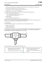
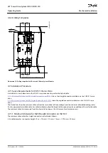
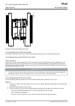
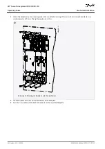
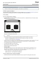
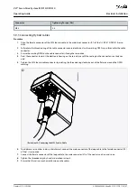
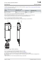
Illustration 30: Pressing the Module onto the Backlink Connector
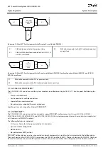
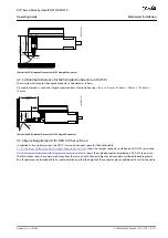
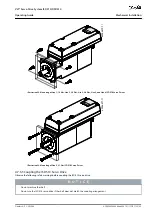
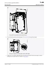
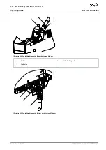
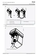
To secure the module, pull down the holding clamp ([1] in
) at the top of the backplate.
1
e3
0b
g8
15
.1
0
STATUS PSM
DEV
SVS ST
NET ST
LINK/ACT
X1
X2
STATUS DAM
DEV
SVS ST
NET ST
AUX
LINK/ACT
X1
X2
X3
STATUS DAM
DEV
SVS ST
NET ST
AUX
LINK/ACT
X1
X2
X3
LCP
LCP
LCP
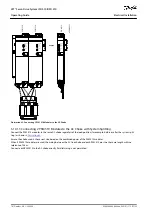
Illustration 31: Pulling Down the Holding Clamp at the Top of the Backplate
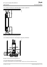
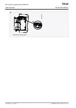
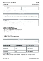
Repeat steps 4, 5, and 6 for the remaining modules, ensuring that the lip at the left side of the 2nd module is inside the
guiding groove at the right side of the 1st module ([1] in
AQ262449648484en-000101 / 175R1135 | 59
Danfoss A/S © 2020.08
Mechanical Installation
VLT® Servo Drive System ISD 510/DSD 510
Operating Guide

