1
26
117
80
10
20
87
18
10
7
2
3
4
5
6
7
8
9
e3
0b
g8
06
.1
0
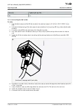
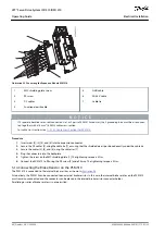
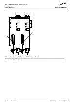
Illustration 49: Feed-In Cable
1
Shielded area
2
UDC+ (black, 2.5 mm
2
/4 mm
2
)
3
UDC– (gray, 2.5 mm
2
/4 mm
2
)
4
STO+ (pink, 0.5 mm
2
)
5
STO– (gray, 0.5 mm
2
)
6
AUX+ (red, 2.5 mm
2
)
7
AUX– (blue, 2.5 mm
2
)
8
Ethernet/fieldbus (green, RJ45 connector)
9
PE (yellow/green, 2.5 mm
2
/4 mm
2
, fork lug)
1
2
3
4
5
6
e3
0b
g8
07
.1
0
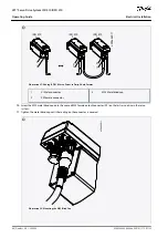
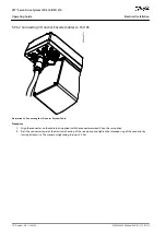
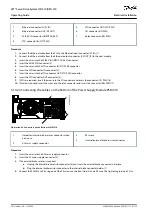
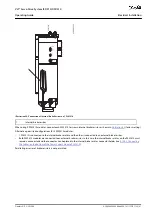
Illustration 50: Connecting the Feed-In Cable
1
Feed-in cable PE screws
2
Bus connector
3
Cable tie for feed-in cable
4
Cable tie for STO cable
5
EMC plate
6
EMC plate screw
AQ262449648484en-000101 / 175R1135
78 | Danfoss A/S © 2020.08
Electrical Installation
VLT® Servo Drive System ISD 510/DSD 510
Operating Guide

