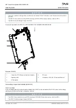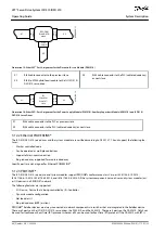
ordered, a RJ45 cover will be mounted to the X3 OUT port. Remove this cover to enable use of the X3 OUT port required for switch-
ing to RT protocol.
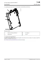
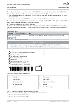
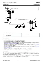
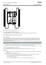
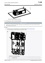
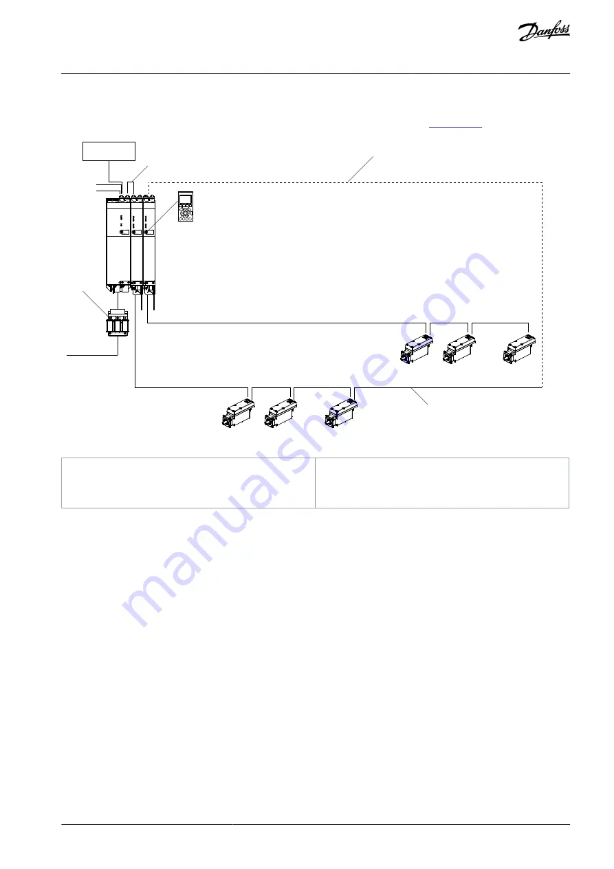
The wiring concept for the use of multiple DAM 510 modules in a single application is shown in
AC 400–480 V
ISD 510
. . .
ISD 510
. . .
Status
Hand
On
Off
Reset
Auto
On
OK
Ba
ck
Can
cel
In
fo
Quick
Menu
Main
Menu
Alarm
Log
LCP
PSM
510
DAM
510
DAM
510
STATUS PSM
LINK/ACT
LCP
LCP
LCP
DEV
SVS ST
NET ST
X1
X2
STATUS DAM
LINK/ACT
DEV
SVS ST
NET ST
AUX
X1
X2
X3
STATUS DAM
LINK/ACT
DEV
SVS ST
NET ST
AUX
X1
X2
X3
PLC
2
e3
0b
i2
75
.1
0
UDC + Real-Time Ethernet Bus + STO + UAUX
UDC + Real-Time Ethernet Bus + STO + UAUX
1
24/48 V
STO
Real-Time Ethernet Bus + STO
3
Illustration 17: Wiring Concept for Multiple DAM 510 Modules
1
AC line choke
2
Customer cable
3
Fieldbus extension cable
AQ262449648484en-000101 / 175R1135 | 47
Danfoss A/S © 2020.08
System Description
VLT® Servo Drive System ISD 510/DSD 510
Operating Guide


