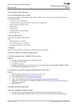
5.
1.
2.
3.
4.
1
e3
0b
g8
15
.1
0
STATUS PSM
DEV
SVS ST
NET ST
LINK/ACT
X1
X2
STATUS DAM
DEV
SVS ST
NET ST
AUX
LINK/ACT
X1
X2
X3
STATUS DAM
DEV
SVS ST
NET ST
AUX
LINK/ACT
X1
X2
X3
LCP
LCP
LCP
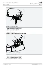
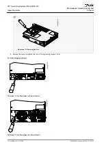
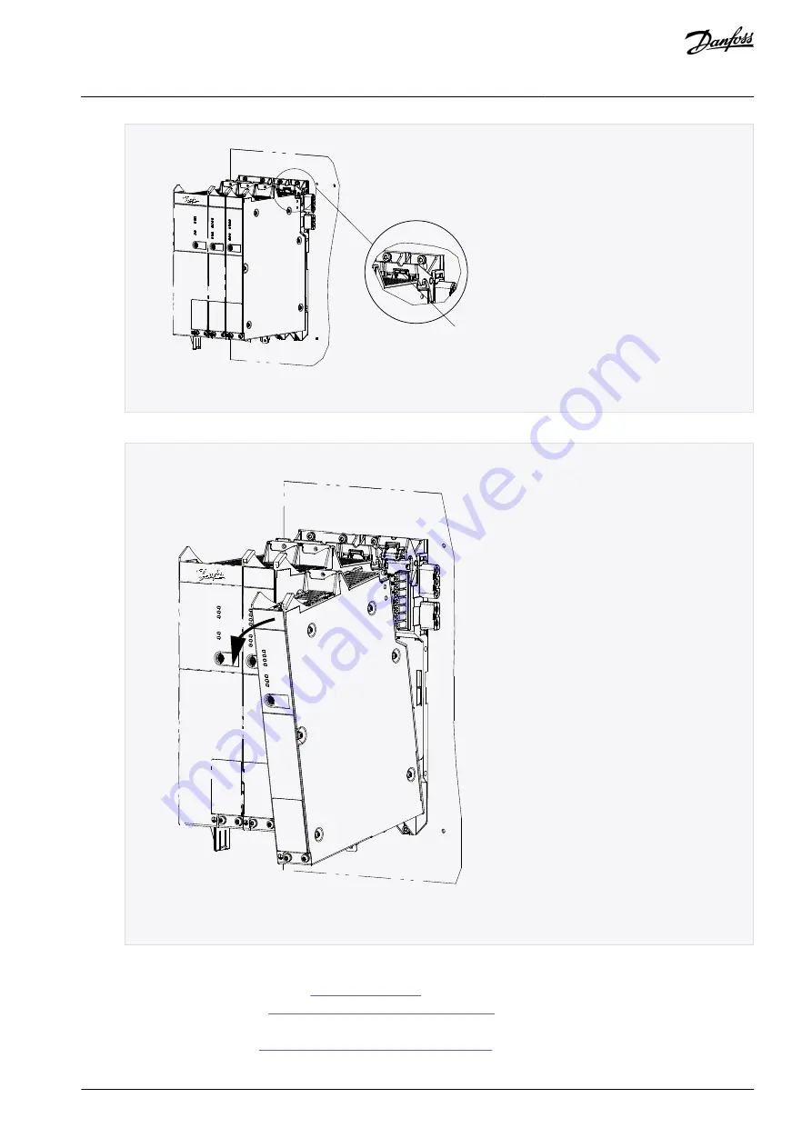
Illustration 112: Releasing the Securing Clamp
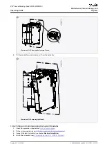
Tilt the module forward and remove it from the backplate.
X2
e3
0b
g8
16
.1
0
STATUS PSM
DEV
SVS ST
NET ST
LINK/ACT
LIN
S
X2
LCP
STATUS DAM
DEV
SVS ST
NET ST
AUX
LINK/ACT
X1
X1
X
X2
X3
X3
LCP
Illustration 113: Removing the Module
10.6.2 Fitting and Commissioning the System Modules
Check if preparation is required (see
Fit the system modules (see
4.7.7 Fitting Instructions for System Modules
Connect the electrical cables (see chapter
Electrical Installation
).
Switch the system on (see
6.8 Switching on the ISD 510/DSD 510 System
).
AQ262449648484en-000101 / 175R1135 | 179
Danfoss A/S © 2020.08
Maintenance, Decomissioning, and
Disposal
VLT® Servo Drive System ISD 510/DSD 510
Operating Guide

