1.
2.
3.
4.
5.
6.
1.
2.
3.
4.
5.
-
-
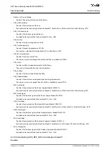
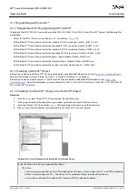
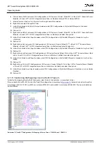
Procedure (Example for an ISD 510 servo drive)
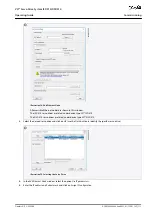
Click on the ISD 510 servo drive entry.
Select the
Slots
tab on the right side of the window.
Remove the current PDO configuration by selecting the entry
Module 1 (CSV PDO)
in the
Slot
box.
Click on
X
.
Select
Library PDO
in the
Module
box.
Click on
<
.
e3
0b
g3
53
.1
1
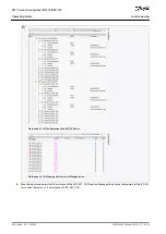
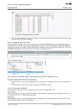
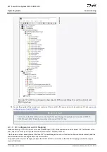
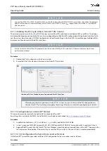
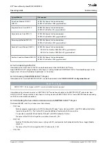
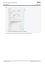
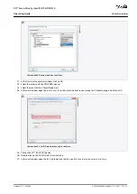
Illustration 71: ISD 510 Servo Drive with Correct I/O Configuration
6.11.12 Attaching the Input and Output Variables to the Physical Data Points
Use the TwinCAT
®
System Manager to attach the input and output variables of the PLC program to the physical inputs and outputs
of the device. This ensures that the library has access to all necessary objects.
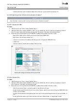
W A R N I N G
Repeat steps 2–22 for Box 1 (VLT
®
Power Supply Module) and the instance
myPSM
.
Repeat steps 2–22 for Box 2 (VLT
®
Decentral Access Module) and the instance
myDAM
.
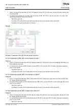
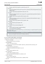
Procedure
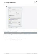
Select
Library TxPDO
via menu [I/O-Configuration
→
I/O Devices
→
Device1 (EtherCAT)
→
Box 1 (VLT Decentral Access
Module)
→
Drive 1 (VLT ISD 510 Integrated Servo Drive)
→
Module 1 (Library PDO)
→
Library TxPDO].
Select all entries
Lib pdo tx1
to
Lib pdo tx9
on the right side of the window.
e3
0b
h5
19
.1
0
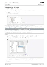
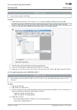
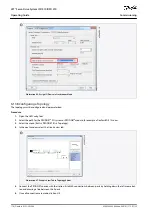
Illustration 72: Attaching Inputs and Outputs to the Physical Data Points
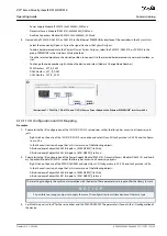
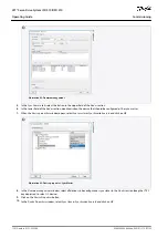
Right-click and select
Change Multi Link...
.
In the
Attach Variable 36.0 Byte(s) (Input)
window, select [PLC-Configuration
→
MyFirstFlexMotionProject
→
Standard
→
.myAxis.TPDO]. Ensure that the
Matching Size
option is selected in the
Attach Variable
window.
Click on
OK
.
AQ262449648484en-000101 / 175R1135 | 103
Danfoss A/S © 2020.08
Commissioning
VLT® Servo Drive System ISD 510/DSD 510
Operating Guide

