-
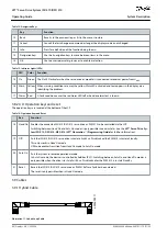
3.9.3 I/O and/or Encoder Cable
This cable connects the I/O and/or encoder to the ISD 510/DSD 510 servo drive (X4 connector). The cable is not included with the
servo drives.
I/O and/or encoder cables with M12 connectors can be used for the ISD 510/DSD 510 system if they comply with the form factor
defined in IEC 61076-2-101.
3.9.4 Fieldbus Extension Cable
Cable length: 2 m
Maximum length to next port: 100 m
If this cable is not used, fit the M23 blind cap to the X2 female connector on the last ISD 510/DSD 510 servo drive in the application.
3.9.5 LCP Cable
The LCP cable connects the LCP to the advanced ISD 510/DSD 510 servo drive and the system modules via an M8 connector.
The LCP cable can be purchased from Danfoss (see the
VLT® Servo Drive System ISD 510, DSD 510, MSD 510 (VLT® Flexmotion
™
)
Design Guide
for further information and ordering numbers).
3.10 Cable Layout and Routing
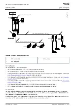
The ISD 510/DSD 510 servo drives are interconnected by hybrid loop cables. A hybrid feed-in cable with quick-release connectors
provides the supply voltage from the Decentral Access Module (DAM 510) to the 1st servo drive.
Routing in drag chains
The hybrid cable is compatible with drag chains and therefore suitable for use in moving systems. The number of bending cycles is
dependent on individual conditions and must therefore be determined in advance for each application, see
for
further information.
3.10.1 Standard Cabling Concept for 2 Lines
This cabling concept is for 2 lines, without redundancy for ISD 510/DSD 510 servo drives in an application. For each additional line of
servo drives, 1 additional DAM 510 is required. For cabling concepts with only 1 line, only 1 DAM 510 is required.
N O T I C E
For cabling with redundancy, see the
VLT® Servo Drive System ISD 510, DSD 510, MSD 510 (VLT® Flexmotion
™
) Design
Guide
.
AQ262449648484en-000101 / 175R1135 | 43
Danfoss A/S © 2020.08
System Description
VLT® Servo Drive System ISD 510/DSD 510
Operating Guide


