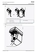
1.
2.
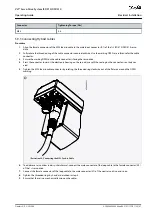
1.
2.
3.
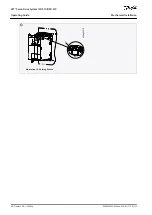
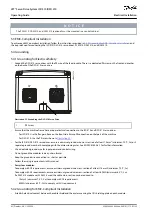
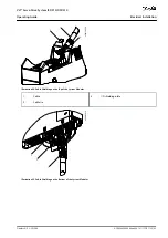
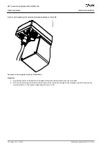
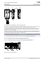
5.9.5.4 Connecting the 3rd Ethernet Device Cable to Port X3
e
3
0
b
e
6
6
8
.1
1
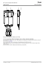
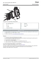
Illustration 41: Connecting the 3
rd
Ethernet Device Cable
Procedure
Align the connector on the cable with the Ethernet connector marked X3 on the ISD 510/DSD 510 servo drive.
Press the connector towards the electronic housing of the servo drive and tighten the threaded ring by turning it clockwise.
The maximum tightening torque is 0.2 Nm.
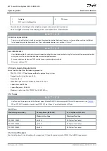
5.9.6 Disconnecting Cables from Ports X3, X4, and X5
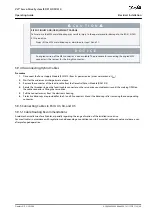
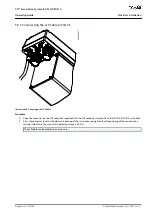
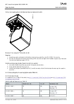
Loosen the threaded ring of the connector by turning it counterclockwise.
Disconnect the cable from the servo drive.
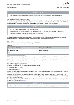
Protective blind caps are provided for the X3, X4, and X5 connectors. Mount the blind caps after removing the respective
connector.
5.10 Connecting the Power Supply Module PSM 510
5.10.1 AC Line Choke
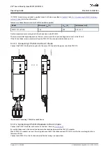
It is mandatory to use a 3-phase AC line choke (see
5.10.1.1 Connecting 1 PSM 510 to the AC Choke
and
Table 23: Line Choke Characteristics for 1 PSM 510
Model
Minimum I
rms
[A]
U
rms
[V]
Inductance [mH]
PSM 510 (10 kW)
20
500
Minimum: 0.47
Maximum: 1.47
PSM 510 (20 kW)
40
500
Minimum: 0.47
Maximum: 1.47
PSM 510 (30 kW)
60
500
0.47 ±10%
AQ262449648484en-000101 / 175R1135
72 | Danfoss A/S © 2020.08
Electrical Installation
VLT® Servo Drive System ISD 510/DSD 510
Operating Guide

