•
•
•
•
•
•
•
•
•
•
•
•
•
•
•
•
•
•
•
•
-
9 Diagnostics
9.1 Faults
If faults occur during the operation of the ISD 510/DSD 510 system, check:
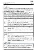
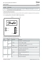
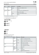
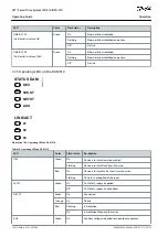
The LEDs on the servo drives for general problems relating to communication or device status.
The LEDs on the PSM 510 and DAM 510 for general problems with communication, auxiliary supply, or STO voltage.
The error codes.
The error codes can be read using the VLT
®
Servo Toolbox software, the LCP, or the PLC. The LCP only shows faults relating to the
device it is connected to.
N O T I C E
If the fault cannot be eliminated by 1 of the measures listed in the troubleshooting tables, notify Danfoss Service.
Have the following information available to enable Danfoss to provide help quickly and effectively:
Type number
Error code
Firmware version
System setup (for example, number of servo drives, system modules, and lines).
System status when the fault occurred.
Ambient conditions.
9.2 Troubleshooting
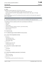
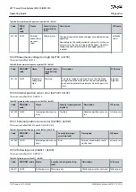
9.2.1 Troubleshooting for the ISD 510/DSD 510 Servo Drives
9.2.1.1 Drive not Running/Starting Slowly
Possible Cause
Bearing wear.
Incorrect parameter settings.
Incorrect control loop parameters.
Incorrect torque settings.
Troubleshooting
Check the bearings and the shaft.
Check the parameter settings.
9.2.1.2 Drive Hums and Draws High Current
Possible Cause
Drive defective.
Troubleshooting
Contact Danfoss.
9.2.1.3 Drive Stops Suddenly and Restart is not Possible
Possible Cause
No drive communication.
Servo drive in error mode.
Troubleshooting
Check the fieldbus connection and the LEDs on the servo drive.
AQ262449648484en-000101 / 175R1135 | 155
Danfoss A/S © 2020.08
Diagnostics
VLT® Servo Drive System ISD 510/DSD 510
Operating Guide

