•
•
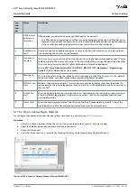
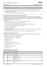
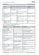
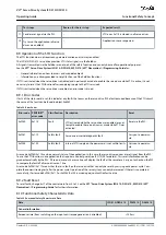
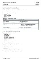
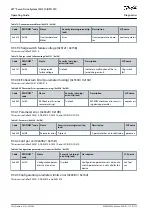
Test steps
Reason for the test step
Expected result
11 Send a reset signal via the PLC.
–
STO error 0x11E is cleared in all servo drives.
12 Try to run the application (all servo
drives are enabled).
–
Application runs as expected.
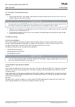
8.9 Operation of the STO Function
The STO function does not require any parameterization and is always enabled.
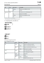
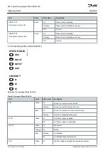
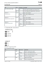
The ISD 510/DSD 510 servo drive provides STO status signals via the fieldbus.
All signals transmitted via the fieldbus are not part of the safety function and can only be used for operational purposes.
See the
VLT® Servo Drive System ISD 510, DSD 510, MSD 510 (VLT® Flexmotion
™
) Programming Guide
for:
General information on how to access and map data objects.
Information on a library provided to simplify the use of the fieldbus functions.
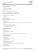
If STO is activated when the servo drive is disabled, and no attempt is made to enable the servo drive while STO is active, it is not
necessary to reset the STO function after reapplying supply to the STO terminals.
If STO is activated when the servo drive is enabled, an error code is issued.
8.9.1 Error Codes
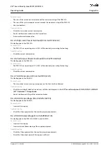
If bit 3 of the statusword is set, this indicates any faults that occur on the servo drive. If the fault occurred because of the STO circuit,
the cause of the fault can be found in object 0x603F.
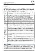
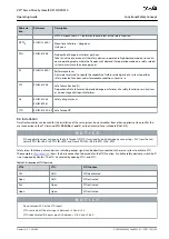
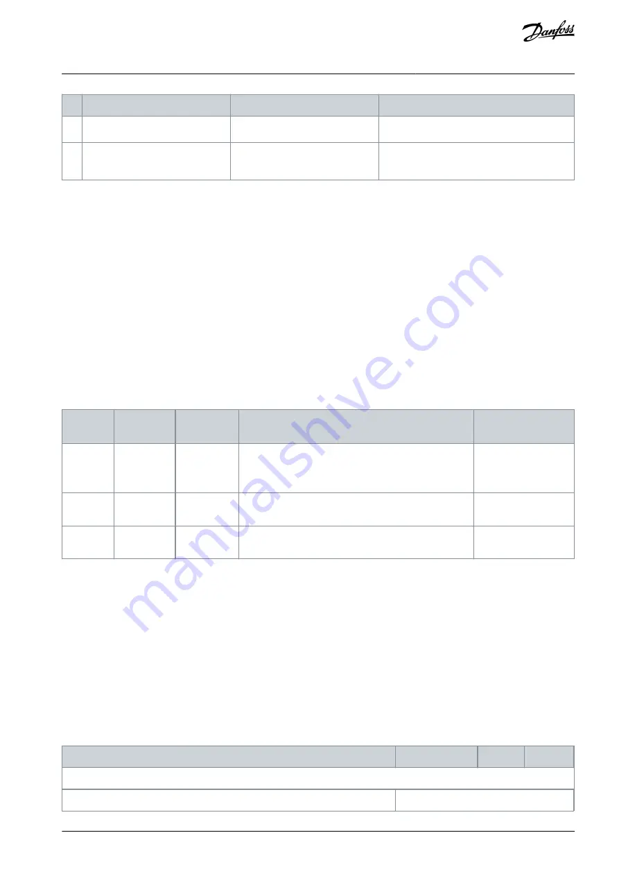
Table 38: Error Codes
Error code PROFINET
®
error code
Classification Description
Reset
0xFF80
0x11E
Fault
STO activated while the servo drive was enabled, or an at-
tempt to enable the servo drive was made while STO was
activated.
Reset via the PLC.
0xFF81
0x11F
Safety fault
Servo drive internal diagnostic fault.
Carry out a power cy-
cle.
0xFF85
0x120
Safety fault
Internal STO supply on the power card is not within limits. Carry out a power cy-
cle.
Error code 0xFF80/0x11E can be a normal status of the application. In this case, the servo drive requires a reset signal from the PLC.
To use the STO function in an application that requires a control guard (see ISO 12100 for details), this reset information can be
given automatically by the PLC. All servo drives on the same line will display this fault at the same time. Carry out a check on the PLC
to compare the fault of all servo drives on 1 line.
Error code 0xFF81/0x11F means that there is a fault on the servo drive that can only be reset by carrying out a power cycle. Com-
plete the commissioning test after the power cycle. Operation of the servo system can only be resumed if the test is completed
successfully. If error code 0xFF81/0x11F or 0xFF85/0x120 is issued again, contact Danfoss Service.
8.9.2 Fault Reset
To reset faults, change bit 7 of the controlword from 0 to 1. See the
VLT® Servo Drive System ISD 510, DSD 510, MSD 510 (VLT®
Flexmotion
™
) Programming Guide
for further information.
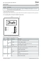
8.10 Functional Safety Characteristic Data
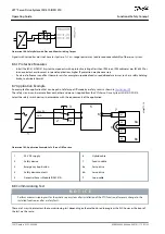
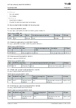
Table 39: Functional Safety Characteristic Data
Data
ISD 510/DSD 510
PSM 510
DAM 510
General information
Response time (from switching on the input until torque generation is disabled)
<100 ms
AQ262449648484en-000101 / 175R1135 | 153
Danfoss A/S © 2020.08
Functional Safety Concept
VLT® Servo Drive System ISD 510/DSD 510
Operating Guide

