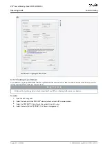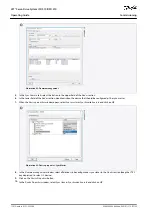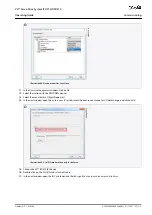
1.
2.
3.
4.
5.
6.
e
3
0
b
g
3
6
4
.1
0
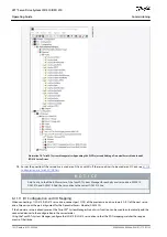
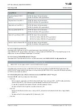
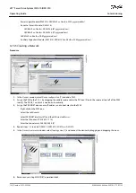
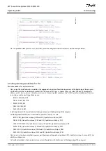
Illustration 86: Assign IO Device in Isochronous Mode
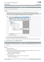
6.13.8 Configuring a Topology
The topology must be configured and parameterized.
Procedure
Open the
HW Config
tool.
Select the path for the PROFINET
®
I/O system or PROFINET
®
module, for example a DanfossISD 510 series.
Select the menu [Edit
→
PROFINET IO
→
Topology].
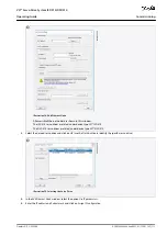
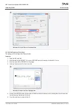
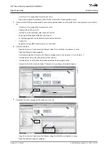
In the next window, select the
Graphic view
tab.
e3
0b
h5
29
.1
0
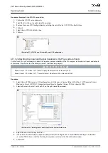
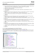
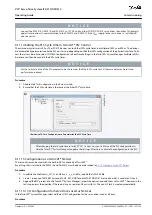
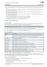
Illustration 87: Graphic View Tab in Topology Editor
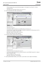
Connect the PROFINET
®
device with the station. Establish connections between ports by holding down the left mouse but-
ton and drawing a line between the 2 ports.
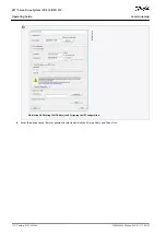
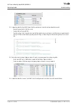
Once all connections are made, click on
OK
.
AQ262449648484en-000101 / 175R1135
116 | Danfoss A/S © 2020.08
Commissioning
VLT® Servo Drive System ISD 510/DSD 510
Operating Guide

