11.1.2.2
11.2
11.2.1
11.2.2
11.2.3
11.2.4
11.2.5
11.2.6
11.3
11.3.1
11.3.2
11.3.3
11.3.4
11.3.5
11.3.6
11.3.7
11.4
11.5
11.6
11.7
11.8
11.8.1
11.8.2
11.8.3
11.8.4
11.8.5
11.9
11.9.1
11.9.2
11.9.2.1
11.9.3
11.9.3.1
11.9.3.2
11.9.4
11.9.4.1
11.9.5
11.9.5.1
11.9.6
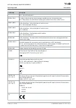
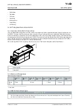
Example Nameplate on the Side of the System Modules
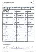
Characteristic Data for ISD 510 Servo Drive without Brake
Characteristic Data for ISD 510 Servo Drive with Brake
Characteristic Data for DSD 510 Servo Drive
Characteristic Data for Power Supply Module (PSM 510)
Characteristic Data for Decentral Access Module (DAM 510)
Characteristic Data for Auxiliary Capacitors Module (ACM 510)
ISD 510 Servo Drive Flange Dimensions
Dimensions of ISD 510 Servo Drive
Dimensions of DSD 510 Servo Drive
Dimensions of Power Supply Module (PSM 510)
Dimensions of Decentral Access Module (DAM 510)
Dimensions of Auxiliary Capacitors Module (ACM 510)
Dimensions of Expansion Module (EXM 510)
Motor Overtemperature Protection
Permitted Forces on the ISD 510 Servo Drive Shaft
Connectors on the ISD 510/DSD 510 Servo Drive
X1 and X2: Hybrid Connector (M23)
X3: 3rd Ethernet Connector (M8, 4 pole)
X4: I/O and/or Encoder Connector (M12, 8 pole)
X5: LCP Connector (M8, 6 pole)
X6: Standard/HIPERFACE DSL Motor Connector
Connectors on the System Modules
Brake Resistor Connector on PSM 510
Ethernet Connectors on PSM 510 and ACM 510
Ethernet Connectors on DAM 510
I/O Connector on PSM 510/ACM 510
24/48 V Cable Cross Sections for PSM 510
AQ262449648484en-000101/175R1135
14 | Danfoss A/S © 2020.08
Contents
VLT® Servo Drive System ISD 510/DSD 510
Operating Guide


