•
•
STATUS PSM
DEV
SVS ST
NET ST
LINK/ACT
X1
X2
LCP
1
e3
0b
h4
23
.1
0
PS
M
5
10
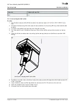
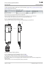
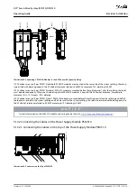
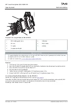
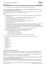
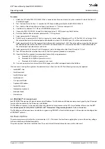
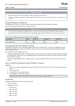
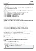
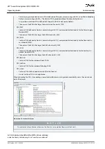
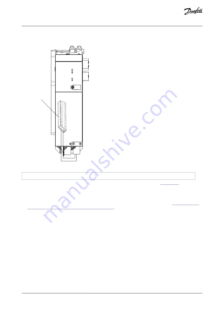
Illustration 54: Connection of Internal Brake Resistor on 1 PSM 510
1
Internal brake resistor
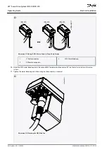
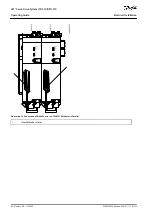
When using 2 PSM 510 modules, connect each PSM 510 to its own internal brake resistor as shown in
(factory setting).
Alternative permitted configurations for 2 PSM 510 modules:
1 PSM 510 is connected to the internal brake resistor and the other is connected to an external brake resistor.
Both PSM 510 modules are connected to an external brake resistor. In this case, the internal brake resistor on the PSM 510 must
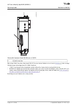
remain unconnected and the connector can be placed in the internal brake resistor connector holder (see
the Cables on the Bottom of the Power Supply Module PSM 510
).
Paralleling or series of brake resistors is not permitted.
AQ262449648484en-000101 / 175R1135 | 81
Danfoss A/S © 2020.08
Electrical Installation
VLT® Servo Drive System ISD 510/DSD 510
Operating Guide

