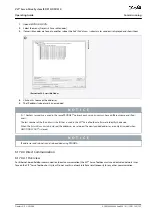
•
•
1.
2.
3.
4.
-
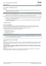
Minimum hardware requirements: 512 MB RAM, Intel Pentium 4 with 2.6 GHz or equivalent, 20 MB hard disk space.
Recommended hardware requirements: Minimum 1 GB RAM, Intel Core i5/i7 or compatible.
6.17.3 Installing the VLT® Servo Toolbox Software
Administrator rights are required to install the software with the Windows operating system. If necessary, contact your system ad-
ministrator.
Procedure
Check that your system meets the system requirements specified in
.
Download the VLT
®
Servo Toolbox installation file from the Danfoss website.
Right-click on the .exe file and select
Run as administrator
.
Follow the on-screen instructions to complete the installation process.
6.17.4 VLT® Servo Toolbox Communication
6.17.4.1 Overview
This chapter describes the Ethernet-specific network interface settings needed by the VLT
®
Servo Toolbox. There are 2 basic commu-
nication methods: direct communication and indirect communication. Their particular network settings are described in the respec-
tive subchapters.
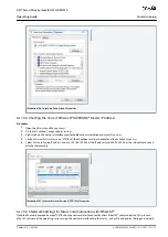
Read and perform the steps with care. Incorrect network configurations can lead to loss of connectivity of a network interface.
6.17.4.2 Firewall
Depending on the firewall settings and the fieldbus used, the messages sent and received by the VLT
®
Servo Toolbox may be
blocked by the firewall on the VLT
®
Servo Toolbox host system. This may lead to a loss of communication and the inability to com-
municate with the devices on the fieldbus. Therefore, ensure that the VLT
®
Servo Toolbox is allowed to communicate through the
firewall on the VLT
®
Servo Toolbox host system. Inappropriate changes to firewall settings may lead to security issues.
N O T I C E
When using a dedicated network interface, the VLT
®
Servo Toolbox must be allowed to communicate specifically through
this network interface.
6.17.4.3 Indirect Communication
6.17.4.3.1 Overview
Communication between ISD 510/DSD 510 devices and the VLT
®
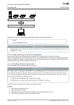
Servo Toolbox through a PLC is called indirect communication.
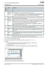
Ethernet-based fieldbus communication (marked A in the graphic) takes place between the PLC and the ISD 510/DSD 510 devices.
However, there is non-fieldbus communication between the PLC and the VLT
®
Servo Toolbox host system.
In the scenario shown, the PLC has the master function and uses cyclic communication with the devices. Therefore, not all function-
alities of the VLT
®
Servo Toolbox, for example the drive control, can be used.
The restrictions when using indirect communication are detailed in the
VLT® Servo Drive System ISD 510, DSD 510, MSD 510 (VLT®
Flexmotion
™
) Programming Guide
.
AQ262449648484en-000101 / 175R1135
132 | Danfoss A/S © 2020.08
Commissioning
VLT® Servo Drive System ISD 510/DSD 510
Operating Guide


