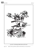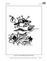
MC012C-BS00 UNITIZED TRANSAXLE WITH DIFFERENTIAL LOCK
Axle Shaft
2006-2010 Turf/Carryall 272/472 and XRT 1200/1200 SE Maintenance and Service Manual
Page 16-3
16
Neutral Lockout
The neutral lockout feature is not a serviceable component on key-start vehicles. The neutral lockout should
remain in the correct position at all times.
See Lockout Cam, Section 11, Page 11-5.
Governor System
The governor system regulates vehicle ground speed. It is mounted inside the unitized transaxle and is driven
by transaxle gears. If any of the governor linkages are removed in order to service other components, read-
justment of the governor linkage is required.
See Governor Cable Installation and Adjustment,
Unitized Transaxle Service
The unitized transaxle is extremely durable and should require very little service under normal operating con-
ditions. The only service required is to maintain proper lubricant level.
See Periodic Lubrication Schedule,
AXLE SHAFT
See General Warning, Section 1, Page 1-1.
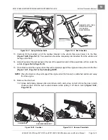
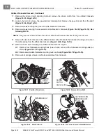
Removal of the unitized transaxle is not required for servicing or replacing axle shafts, axle bearings, or axle
shaft oil seals. If the unitized transaxle is to be removed from the vehicle, then do not remove the wheels, axle
shafts, or axle tubes first. Instructions for removing the unitized transaxle from the vehicle begin on page 16-6.
AXLE SHAFT, BEARING, AND OIL SEAL REMOVAL
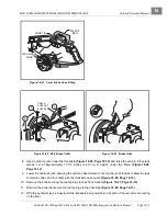
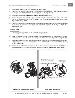
1. Chock the front wheels and lift the rear of the vehicle with a floor jack. Then place jack stands under the
axle tubes to support the vehicle.
See WARNING “Lift only one end of the vehicle...” in General
2. Remove the wheel from the vehicle.
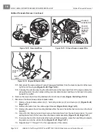
3. Remove the brake drum. If the brake drum was easily removed, proceed to step 5.
4. To remove tight brake drums:
4.1. Locate the bolt heads for the two brake shoe adjusters on the back of each brake cluster assembly.
4.2. Use a torque wrench and a Torx #T-27 driver, or hydraulic brake adjuster (CC P/N 102169401), and
gently rotate the adjuster bolt to increase the clearance between the brake shoes and the brake
drum.
See Figure 6-2, Section 6, Page 6-7.
4.3. Rotate the brake drum slightly and remove it from the brake shoe cluster assembly.
Содержание CARRYALL 272
Страница 2: ......
Страница 14: ......
Страница 18: ...1...
Страница 52: ...5...
Страница 90: ...6...
Страница 110: ...7...
Страница 112: ...8...
Страница 128: ...10...
Страница 170: ...11...
Страница 224: ...13...
Страница 284: ...16...
Страница 302: ...17...
Страница 308: ......
Страница 309: ...Club Car R NOTES...
Страница 310: ...Club Car R NOTES...
Страница 311: ......


