MC012C-BS00 TRANSAXLE: HYDRAULIC AND PARK BRAKE SYSTEMS
Hydraulic Line and Hose Replacement
Page 6-24
2006-2010 Turf/Carryall 272/472 and XRT 1200/1200 SE Maintenance and Service Manual
6
Front Brake Line Installation, Continued:
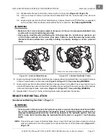
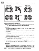
4. Tighten the flare nut (4) to the master cylinder to 11 ft-lb (14.9 N·m).
5. Tighten the flare nut (4) to the T-manifold block (1) to 11 ft-lb (14.9 N·m).
6. Fill the reservoir of the master cylinder and bleed the hydraulic system.
7. Perform all of the brake system inspections.
See Brake System Inspection on page 6-1.
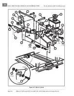
FRONT BRAKE HOSE ASSEMBLY REMOVAL
NOTE:
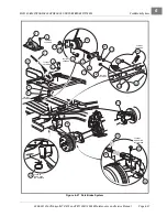
If either of the two front brake hoses or the T-manifold block (1) are found to be damaged, the entire
assembly must be replaced
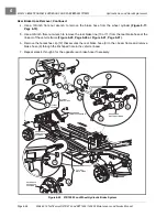
1. Chock the rear wheels, release the park brake and lift the front of the vehicle with a chain hoist or floor
jack.
See WARNING “Lift only one end...” in
General Warning, Section 1, Page 1-2
2. Place jack stands under the outer front frame I-beams and lower onto stands.
3. Place a pan below the vehicle to collect the brake fluid.
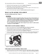
4. Remove the banjo bolt (5) and two copper washers (6) from the front wheel cylinder assemblies
. Discard the copper washers (6).
5. Remove the bolt (2), locknut (3), front hose bracket and weldment steering stop (34) from where the bot-
tom of the shock connects to each of the front A-arms.
See Figure 7-28, Section 7, Page 7-17.
6. Use a 3/8-inch flare nut wrench to remove the brake line (4) from the T-manifold block (1)
.
7. Remove the bolt (2), washer (13) and locknut (3) that secure the T-manifold block (1) to the shock tower.
FRONT BRAKE HOSE ASSEMBLY INSTALLATION
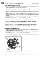
1. Install the 1/4-20 x 1-1/4-inch hex-head bolt (2) and nylon locknut (3), washer (13), T-manifold block (1)
to frame bracket. Tighten to 76 in-lb (8.6 N·m)
.
2. Connect brake hoses with new copper washers (6) and banjo bolts (5). Position the elbow of each hose
toward the rear of the vehicle. Tighten bolts to 13 ft-lb (17.6 N·m).
3. Attach front hose brackets, steering stop weldments (34), and lower shock absorber mounts using bolts
(2), and locknuts (3). Align the steering stops (34) and brake hose brackets with the shock absorbers and
tighten hardware to 20 ft-lb (27 N·m).
See Figure 7-28, Section 7, Page 7-17.
4. Connect the flare fitting on the brake line (4) to the T-manifold block (1). Tighten to 11 ft-lb (14.9 N·m)
5. Fill the reservoir of the master cylinder and bleed the hydraulic system.
6. Perform all of the brake system inspections.
See Brake System Inspection on page 6-1.
REAR BRAKE LINE REMOVAL
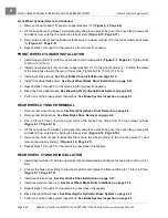
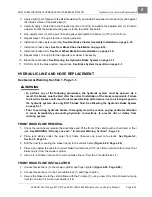
1. Turf 272/Carryall 272/XRT 1200:
1.1. Chock the front wheels, release the park brake, and lift the rear of the vehicle with a chain hoist or
floor jack.
See WARNING “Lift only one end...” in General Warning, Section 1, Page 1-1.
1.2. Place jack stands under the rear axle tubes and lower onto stands.
1.3. Place a pan below the vehicle to collect the brake fluid.
1.4. Use a 3/8-inch flare nut wrench to remove brake line (10 or 11) from the master cylinder
.
Содержание CARRYALL 272
Страница 2: ......
Страница 14: ......
Страница 18: ...1...
Страница 52: ...5...
Страница 90: ...6...
Страница 110: ...7...
Страница 112: ...8...
Страница 128: ...10...
Страница 170: ...11...
Страница 224: ...13...
Страница 284: ...16...
Страница 302: ...17...
Страница 308: ......
Страница 309: ...Club Car R NOTES...
Страница 310: ...Club Car R NOTES...
Страница 311: ......


