MC012C-BS00 TRANSAXLE: HYDRAULIC AND PARK BRAKE SYSTEMS
Master Cylinder and Bell Crank Replacement
Page 6-28
2006-2010 Turf/Carryall 272/472 and XRT 1200/1200 SE Maintenance and Service Manual
6
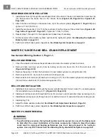
REAR BRAKE HOSE INSTALLATION
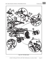
1. Install brake hose (9) through the oval-shaped hole in the vehicle I-beam, and install the horseshoe clip
(12) that secures the brake hose to the I-beam frame
or
.
2. Attach the flare nut fitting on the brake hose (9) to the wheel cylinder
and
tighten to 11 ft-lb (14.9 N·m).
3. Install the rear brake line (10 or 11) to the rear hose (9) at the I-beam of the vehicle frame
or
. Tighten to 11 ft-lb (14.9 N·m).
4. Repeat steps 1 through 3 for the opposite rear brake hose if necessary.
5. Fill the reservoir of the master cylinder and bleed the hydraulic system.
6. Perform all of the brake system inspections.
See Brake System Inspection on page 6-1.
MASTER CYLINDER AND BELL CRANK REPLACEMENT
See General Warning, Section 1, Page 1-1.
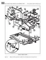
BELL CRANK REMOVAL
1. Chock the wheels and release the park brake and access the master cylinder bell crank.
2. Remove brake rod clevis pin (6), bow tie locking pin (8) and clevis (16) from the bell crank (13)
3. Remove the spring (18) from the bell crank (13) and master cylinder mounting bracket (19).
4. Remove push rod (3), clevis pin (6) and bow tie locking pin (8).
5. Remove bell crank clevis pin (9) and bow tie locking pin (11) from the master cylinder mounting bracket
(19) and remove bell crank (13) and centering spacer (12).
BELL CRANK INSTALLATION
1. Install bell crank clevis pin (9) through the master cylinder bracket (19), bell crank (13), centering spacer
(12) and attach bow tie locking pin (11)
2. Install push rod clevis pin (6) through bell crank (13) and push rod (3) and attach bow tie locking pin (8).
3. Install brake rod clevis pin (6) through clevis (16) and bell crank (13) and attach bow tie locking pin (8).
4. Install spring (18).
5. Adjust the brake pedal as instructed.
See Brake Pedal Adjustment, Section 5, Page 5-3.
6. Perform all of the brake system inspections.
See Brake System Inspection on page 6-1.
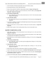
MASTER CYLINDER REMOVAL
ý
WARNING
• To perform this procedure, the hydraulic system must be opened. As a result, the brakes must
be bled after the correct installation of the brake components. Failure to bleed the brakes
could result in decreased braking performance due to air being trapped in the hydraulic
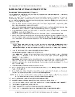
system. Use only DOT 5 brake fluid. See Bleeding the Hydraulic Brake System on page 6-31.
Содержание CARRYALL 272
Страница 2: ......
Страница 14: ......
Страница 18: ...1...
Страница 52: ...5...
Страница 90: ...6...
Страница 110: ...7...
Страница 112: ...8...
Страница 128: ...10...
Страница 170: ...11...
Страница 224: ...13...
Страница 284: ...16...
Страница 302: ...17...
Страница 308: ......
Страница 309: ...Club Car R NOTES...
Страница 310: ...Club Car R NOTES...
Страница 311: ......

