


TROUBLESHOOTING AND ELECTRICAL SYSTEM: FE400, KEY-START ENGINE
Test Procedures
2006-2010 Turf/Carryall 272/472 and XRT 1200/1200 SE Maintenance and Service Manual
Page 11-33
11
TEST PROCEDURE 24 – BATTERY TEST (UNDER LOAD)
See General Warning, Section 1, Page 1-1.
NOTE:
Keep the battery connected while performing this test procedure.
1. Turn the key switch OFF and remove the key. Place the Forward/Reverse handle in the NEUTRAL posi-
tion. Chock the wheels.
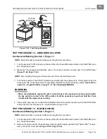
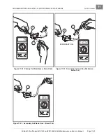
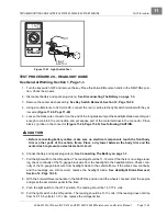
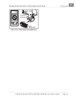
2. Set a multimeter to 20 volts and place the red (+) probe on the F2 (white wire) terminal on the starter/gen-
erator. Place the black (–) probe on the negative battery post.
3. Turn the key switch to the START position and hold it in the START position while noting the voltage read-
ing on the multimeter (with the key in the START position the battery is under load).
3.1. If the voltage reading is over 9.6 volts at 70 °F (21 °C) (electrolyte temperature) check the starter/
generator.
See following NOTE
.
NOTE:
The voltage reading is taken at 70 °F (21 °C). At lower electrolyte temperatures the voltage reading
will be lower.
3.2. If the reading is below 9.6 volts at 70 °F (21 °C) (electrolyte temperature), check the battery.
Test Procedure 1 – Battery on page 11-11.
3.3. If the reading is zero, there may be NO continuity across the large posts of the solenoid.
Procedure 6 – Solenoid on page 11-17.
4. If all of the test results are good and the voltage reading is zero, there may be a broken or damaged 6-
gauge white wire from the solenoid to the starter/generator.
See Test Procedure 8 – Starter/Generator
(Starter Function) on page 11-19.
TEST PROCEDURE 25 – FUEL LEVEL SENDING UNIT
See General Warning, Section 1, Page 1-1.
ý
WARNING
• To avoid the possibility of fire or explosion, make sure the fuel tank cap is securely in place
while performing this test procedure.
1. Turn the key switch to OFF and remove the key. Place the Forward/Reverse handle in the NEUTRAL
position. Chock the wheels.
2. Disconnect battery and spark plug wire(s).
See Disconnecting The Battery on page 1-3.
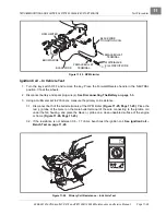
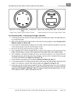
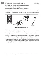
3. Disconnect the orange wire from the center post of the fuel level sending unit.
4. With a multimeter set to 2k ohms, place the red (+) probe of the multimeter on the center post of the send-
ing unit. Place the black (–) probe on the ground connection of the sending unit
.
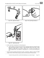
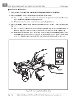
5. The following resistance readings (in ohms) should be obtained depending on the position of the float
inside the fuel tank. The resistance reading will vary according to the exact position of the float. The chart
below may be used as a guideline to determine if the fuel level sending unit is operating correctly. Make
sure the float is at the surface of the fuel in the tank.
FLOAT POSITION
RESISTANCE READING
FUEL GAUGE READINGS
Lower position (tank empty)
240 ± 20 ohms
Empty
Center position (tank half full)
120 ± 20 ohms
Half full
Upper position (tank full)
60 ± 20 ohms
Full
Содержание CARRYALL 272
Страница 2: ......
Страница 14: ......
Страница 18: ...1...
Страница 52: ...5...
Страница 90: ...6...
Страница 110: ...7...
Страница 112: ...8...
Страница 128: ...10...
Страница 170: ...11...
Страница 224: ...13...
Страница 284: ...16...
Страница 302: ...17...
Страница 308: ......
Страница 309: ...Club Car R NOTES...
Страница 310: ...Club Car R NOTES...
Страница 311: ......


