ELECTRICAL COMPONENTS: FE400, KEY-START ENGINE
Lockout Cam
Page 12-28
2006-2010 Turf/Carryall 272/472 and XRT 1200/1200 SE Maintenance and Service Manual
12
LOCKOUT CAM
See General Warning, Section 1, Page 1-1.
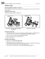
If the cam lobes have worn to the point where they will no longer actuate the lockout cam limit switch, the cam
must be replaced.
Testing the Lockout Cam
See Test Procedure 23, Section 11, Page 11-32.
Lockout Cam Removal
1. Turn the key switch OFF and remove the key. Place the Forward/Reverse handle in the NEUTRAL posi-
Disconnect battery and spark plug wire(s).
See Disconnecting The Battery on page 1-3.
2. Remove the external snap ring (14)
.
3. Remove the plastic washer (12) and the spring (13).
4. Remove the cam (11).
Lockout Cam Installation
1. Install the cam (11)
2. Install the spring (13) and the plastic washer (12).
3. Install the external snap ring (14) into the groove on the shaft. The lockout limit switch should be activated
only when the Forward/Reverse handle is in the NEUTRAL position.
4. Connect battery and spark plug wire(s).
See Connecting The Battery on page 1-3.
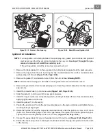
Figure 12-34 Lockout Cam and Reverse Buzzer
Limit Switches
Figure 12-35 Lockout Cam
COM
NC
NO
REVERSE BUZZER
LIMIT SWITCH
LOCKOUT
LIMIT SWITCH
2
4
9
5
6
2
3
FORWARD/REVERSE
ASSEMBLY
CO
M
NC
NO
11
12
5
13
14
FORWARD/REVERSE
ASSEMBLY
4
Содержание CARRYALL 272
Страница 2: ......
Страница 14: ......
Страница 18: ...1...
Страница 52: ...5...
Страница 90: ...6...
Страница 110: ...7...
Страница 112: ...8...
Страница 128: ...10...
Страница 170: ...11...
Страница 224: ...13...
Страница 284: ...16...
Страница 302: ...17...
Страница 308: ......
Страница 309: ...Club Car R NOTES...
Страница 310: ...Club Car R NOTES...
Страница 311: ......

