MC012C-BS00 TRANSAXLE: HYDRAULIC AND PARK BRAKE SYSTEMS
Hydraulic Line and Hose Replacement
2006-2010 Turf/Carryall 272/472 and XRT 1200/1200 SE Maintenance and Service Manual
Page 6-23
6
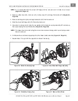
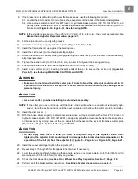
2. Apply a light coat of grease to the Bellville washer (5) and install the washer onto the bolt (4) and against
the inside surface of the back plate (1).
3. Carefully apply Loctite 222 to the threaded portion of bolt (4) and attach the adjuster arm (3). Position
adjuster so that the brake mounting post is to the top of the back plate.
4. Grip adjuster arm (3) with a pair of locking pliers and tighten the bolt (4) to 115 in-lb (13 N·m).
5. Repeat steps 1 through 4 for the remaining adjuster.
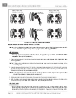
6. Install rear brake cluster assembly.
See Rear Brake Cluster Assembly Installation on page 6-19.
7. Install rear brake shoes.
See Rear Brake Shoe Installation on page 6-12.
8. Install rear brake drum.
See Rear Wheel Brake Drum Installation on page 6-16.
9. Repeat steps 1 through 8 for the opposite rear wheel if necessary.
10. Bleed the rear brakes.
See Bleeding the Hydraulic Brake System on page 6-31.
11. Perform all of the brake system inspections.
See Brake System Inspection on page 6-1.
HYDRAULIC LINE AND HOSE REPLACEMENT
See General Warning, Section 1, Page 1-1.
ý
WARNING
• To perform any of the following procedures, the hydraulic system must be opened. As a
result, the brakes must be bled after the correct installation of the brake components. Failure
to bleed the brakes could result in decreased braking performance due to air being trapped in
the hydraulic system. Use only DOT 5 brake fluid. See Bleeding the Hydraulic Brake System
on page 6-31.
• Prior to servicing hydraulic brakes, thoroughly clean the vehicle, paying particular attention
to areas immediately surrounding hydraulic connections, to prevent dirt or debris from
entering system.
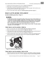
FRONT BRAKE LINE REMOVAL
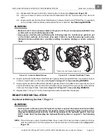
1. Chock the rear wheels, release the park brake and lift the front of the vehicle with a chain hoist or floor
jack.
See WARNING “Lift only one end...” in
General Warning, Section 1, Page 1-2
.
2. Place jack stands under the outer front frame I-beams and lower onto stands.
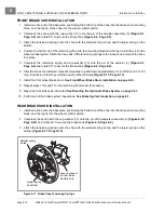
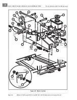
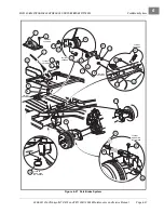
3. Drill the rivet (8) securing the brake line (4) to the vehicle frame
4. Place a pan below the vehicle to collect brake fluid and use a 7/16-inch flare nut wrench to remove front
brake line (4) from the master cylinder.
5. Use a 3/8-inch flare nut wrench to remove brake line (4) from the T-manifold block (1).
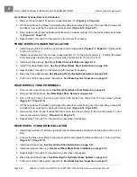
FRONT BRAKE LINE INSTALLATION
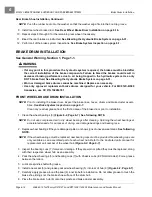
1. Connect brake line (4) to the master cylinder and finger-tighten
.
2. Connect brake line (4) to the T-manifold block (1) and finger-tighten.
3. Secure the brake line to the vehicle frame with the P-clamp (7), using a new 3/6 x 3/4-inch aluminum pop
rivet (8), and two 3/16-inch rivet washers (14).
Содержание CARRYALL 272
Страница 2: ......
Страница 14: ......
Страница 18: ...1...
Страница 52: ...5...
Страница 90: ...6...
Страница 110: ...7...
Страница 112: ...8...
Страница 128: ...10...
Страница 170: ...11...
Страница 224: ...13...
Страница 284: ...16...
Страница 302: ...17...
Страница 308: ......
Страница 309: ...Club Car R NOTES...
Страница 310: ...Club Car R NOTES...
Страница 311: ......

