


FUEL SYSTEM
Choke and Air Intake System
2006-2010 Turf/Carryall 272/472 and XRT 1200/1200 SE Maintenance and Service Manual
Page 14-17
14
INTAKE DUCT INSTALLATION
NOTE:
The intake duct assembly is installed from the front of the vehicle, in reverse order of removal. This
procedure is best accomplished using two people.
See following NOTE.
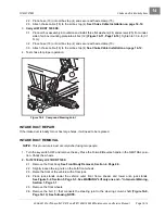
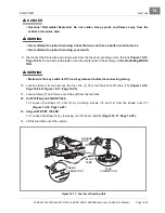
1. Slide the intake duct between the round crossmember and the floorboard, moving it to the rear along the
underside of the floorboard.
See following NOTE.
NOTE:
It is best to have a second person guide the air box end of the duct into position as it is pushed from
the front of the vehicle. Insert the end of the intake duct through the slot in the front of the air box
mounting plate.
2. Secure the front of the duct to the underside of the floorboard with pop rivet (24) and flat washers (25)
3. Place a piece of double-sided adhesive tape on the intake shield and remove the adhesive backing.
See
following NOTE.
NOTE:
If necessary reform any minor deformation of the shield and clean the old double-sided adhesive
tape cleanly from both the shield and vehicle frame before installation of the shield.
4. Install the shield to the frame with the adhesive strip and pop rivet (30).
5. Install air box.
See Air Box Installation on page 14-12.
6. Assemble front end components.
See following NOTE.
NOTE:
This procedure is best accomplished using two people.
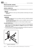
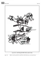
6.1. Attach each of the front A-arms to the shock tower at the top shock mount and bottom hole locations
of the strip plate (27) using bolts (28) and locknuts. Do not tighten
.
6.2. Position the top edge of the strap plate (27) onto the frame and install the two bolts (26), flat wash-
ers and locknuts. Do not tighten.
6.3. Tighten bolts (28) at the shock tower and strip plate (27) to 20 ft-lb (27 N·m).
6.4. Tighten bolts (26) at the top of the strip plate (27) and frame to 20 ft-lb (27 N·m).
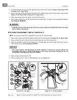
6.5. Install steering joint.
See following NOTE
.
NOTE:
Make sure steering wheel and front wheels are properly aligned before installing steering joint.
The steering column shaft has a machined flat area provided for passage of the bolt when assem-
bled to the steering joint.
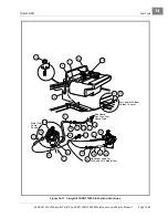
6.6. Slip the splined steering joint over the splined steering column shaft, aligning with the mark made
during disassembly. Attach the bolt (1) through the steering joint flange and loosely attach the nut
.
6.7. Attach the rack and pinion assembly to the shock tower plate using the four bolts (2) and locknuts
. Tighten to 20 ft-lb (27 N·m).
6.8. Tighten the bolt (1) of the steering joint flange to 15 ft-lb (20.3 N·m).
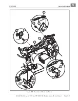
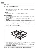
7. Carryall 472/XRT 1200 SE:
7.1. Slide the rear portion of the air duct up under the rear floor board area and through the opening pro-
vided in the bottom of the engine compartment.
7.2. Attach strap (14) on each end with 3/16-inch x 1/2-inch pop rivets (27) and washers (28)
7.3. Attach a long wire tie (23) around the air duct body, Forward/Reverse cable, and choke cable, posi-
tioning the cables between the air duct and vehicle frame.
7.4. Install air box.
See Air Box Installation on page 14-12.
8. Install the front wheels and tighten the wheel lug nuts finger-tight.
Содержание CARRYALL 272
Страница 2: ......
Страница 14: ......
Страница 18: ...1...
Страница 52: ...5...
Страница 90: ...6...
Страница 110: ...7...
Страница 112: ...8...
Страница 128: ...10...
Страница 170: ...11...
Страница 224: ...13...
Страница 284: ...16...
Страница 302: ...17...
Страница 308: ......
Страница 309: ...Club Car R NOTES...
Страница 310: ...Club Car R NOTES...
Страница 311: ......


